
The Unidirectional Flow: Defining Direct Current (DC)
When electrical professionals and DIYers ask what is dc electricity, the most fundamental answer lies in electron behavior. Unlike Alternating Current (AC), where electrons rapidly oscillate back and forth (typically 60 times per second in North America), Direct Current (DC) features a unidirectional flow of electric charge. Electrons move steadily from the negative terminal to the positive terminal through the conductor.
This constant, non-fluctuating flow makes DC the undisputed standard for energy storage, battery banks, solar photovoltaic (PV) arrays, electric vehicles (EVs), and modern DC microgrids. However, from a safety and wiring perspective, treating DC like AC is a catastrophic mistake. The physics governing DC arcs, human shock response, and voltage drop require entirely different engineering controls, overcurrent protection devices (OCPDs), and wire sizing methodologies.
The Hidden Danger: Why DC Arcs Are Harder to Extinguish
The most critical safety distinction between AC and DC electricity is arc sustainability. When you open a disconnect switch or a breaker under a heavy load, the air gap between the separating contacts ionizes, creating a plasma arc.
- In AC Systems: The voltage naturally crosses zero 120 times per second (on a 60Hz system). This 'zero-crossing' inherently starves the plasma of energy, naturally extinguishing the arc in milliseconds.
- In DC Systems: There is no zero-crossing. The continuous voltage actively sustains the plasma channel. If a DC circuit is interrupted without specialized arc-chutes or magnetic blowouts, the arc will stretch, generating temperatures exceeding 10,000°F (5,500°C).
Real-World Failure Mode: Using an AC-rated breaker on a DC battery bank is a leading cause of electrical fires in off-grid solar setups. The AC breaker's internal thermal-magnetic mechanism cannot physically stretch and cool the DC arc fast enough, resulting in the breaker melting, welding its contacts shut, or igniting the surrounding enclosure.
To combat this, DC overcurrent protection requires specialized components. For high-amperage battery banks, Class T fuses (like those from Bussmann or Mersen) are mandatory due to their high interrupting capacity (up to 20,000 amps at 125V DC) and ceramic bodies that contain arc flashes. For switching, you must use DC-rated disconnects featuring magnetic blowouts that physically push the arc into an extinguishing chamber.
Human Body Response: DC vs. AC Shock Hazards
Understanding what DC electricity does to the human body is vital for establishing safe lockout/tagout (LOTO) procedures. According to OSHA's electrical safety guidelines, the physiological response to DC shock differs drastically from AC.
AC current induces muscle tetany—a continuous, involuntary contraction that causes the victim's hand to 'lock on' to the live conductor. DC current, being continuous and unidirectional, typically causes a single, massive convulsive jerk. While this can throw a person away from the source (potentially causing secondary fall injuries), it also means the contact time might be shorter. However, DC is highly prone to causing severe, deep-tissue electrical burns because the constant current flow generates uninterrupted resistive heating in the body's tissues.
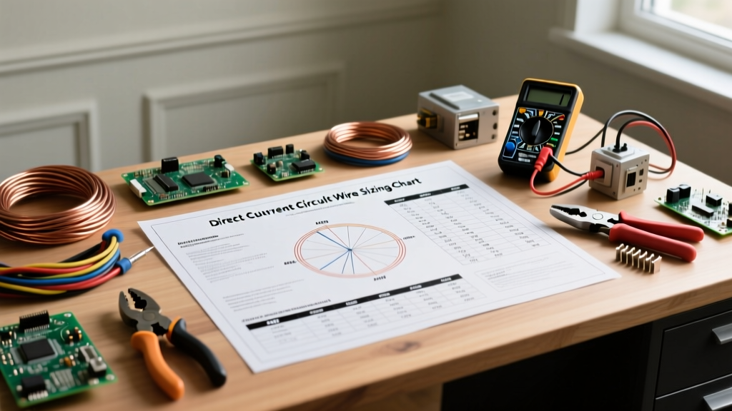
Wire Sizing, Heat, and Voltage Drop in Low-Voltage DC
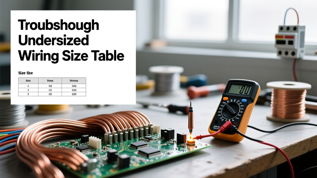
Because DC systems often operate at lower voltages (12V, 24V, 48V) compared to AC mains (120V/240V), they require exponentially higher current to deliver the same wattage. Since resistive heat loss is calculated as I²R (Current squared multiplied by Resistance), high-current DC circuits generate massive amounts of heat if undersized wires are used.
Consider a 2,400W inverter load:
- At 120V AC: The current draw is 20 Amps. A standard 12 AWG copper wire is sufficient and safe.
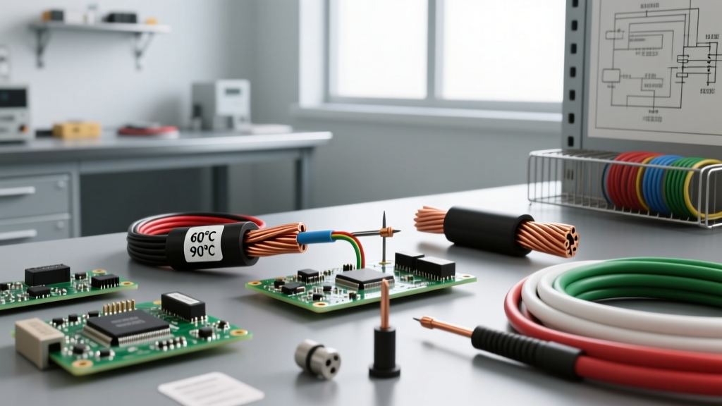
- At 12V DC: The current draw is 200 Amps. You must use 2/0 AWG (or larger) copper wire to prevent the insulation from melting and to keep voltage drop below the critical 3% threshold.
Voltage drop in DC is not just an efficiency issue; it is a safety issue. If voltage drops too low, DC motors and inverter compressors will draw more current to compensate for the missing wattage, leading to a thermal runaway loop that can melt wire terminations.
DC vs. AC Safety & Component Ratings Matrix
| Characteristic | Alternating Current (AC) | Direct Current (DC) |
|---|---|---|
| Waveform Zero-Crossing | 120 times/sec (60Hz) | Never (Continuous) |
| Arc Extinguishing | Natural (Voltage drops to zero) | Requires magnetic blowouts / extreme gaps |
| Breaker Rating | Standard thermal-magnetic | Must be explicitly DC-rated (Polarity sensitive) |
| Shock Response | Tetany (Lock-on effect) | Convulsive jerk (Throw-back effect) |
| Primary Wiring Threat | Overload / Short Circuit | High Amperage Heat / Voltage Drop |
Mandatory DC Safety Protocols for Battery & Solar Arrays
As the electrical industry adapts to the rise of DC microgrids and Energy Storage Systems (ESS), the NFPA 70 National Electrical Code (NEC) has drastically tightened regulations surrounding DC installations (specifically Articles 480 and 690). If you are designing or maintaining DC infrastructure, adhere to these non-negotiable safety protocols:
1. Calibrated Torque Terminations
High-current DC systems are incredibly sensitive to loose connections. A loose terminal increases resistance, which generates localized heat. In a 48V server-rack battery system delivering 100A, a loose M8 busbar bolt can easily reach ignition temperatures. The NEC now mandates the use of calibrated torque screwdrivers and wrenches to achieve the exact manufacturer-specified torque values (e.g., 5 Nm to 7 Nm for typical lithium battery terminals). Always mark torqued bolts with a torque-seal pen for visual inspection.
2. Polarity Verification and Color Coding
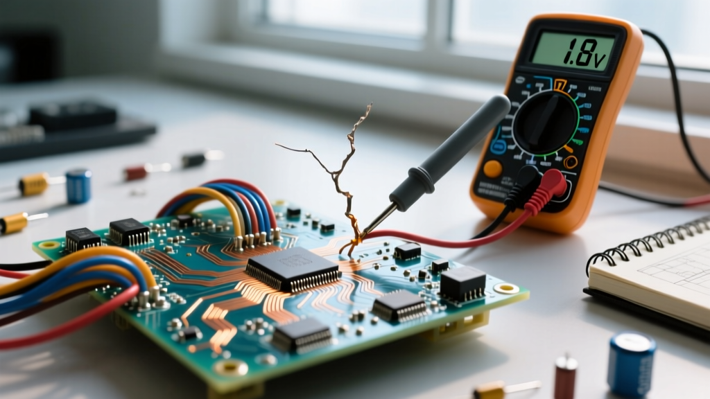
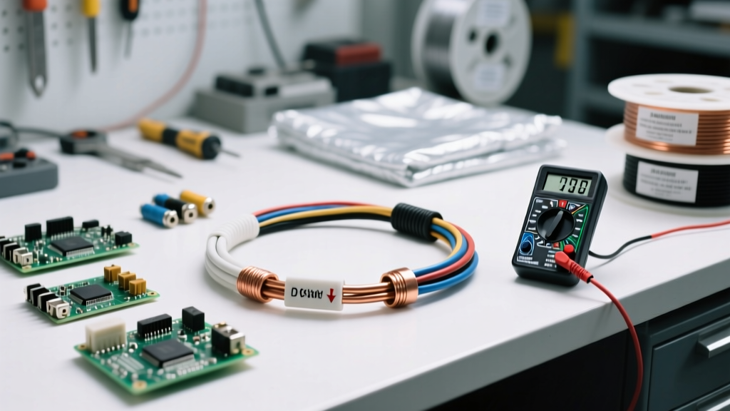
Reversing polarity in a DC system can instantly destroy charge controllers, inverters, and battery management systems (BMS), often resulting in catastrophic component failure or fire. Always use a digital multimeter (DMM) to verify polarity before closing a DC disconnect. Adhere to strict color-coding: Red for ungrounded positive conductors, Black or White for grounded negative conductors (depending on local code and system grounding topology), and Green/Bare for equipment grounding conductors.
3. Proper Fusing Placement
In ungrounded DC systems, overcurrent protection must be installed on all current-carrying conductors. Even in grounded systems, the ungrounded (positive) conductor must be fused as close to the power source (the battery terminal) as practically possible—ideally within 7 inches of the terminal post—to protect the entire downstream cable run from short-circuit faults.
Conclusion: Respecting the Continuous Current
Understanding what DC electricity is goes far beyond basic physics; it is about respecting the relentless, unidirectional nature of the current. DC does not forgive undersized wires, it does not naturally extinguish arcs, and it demands specialized, DC-rated hardware. By prioritizing magnetic arc suppression, meticulous wire sizing for voltage drop, and precise torque terminations, you ensure that your battery banks, solar arrays, and DC microgrids operate safely and reliably for decades.