
Core Fundamentals of a Direct Current Circuit
When designing, building, or troubleshooting a direct current circuit, understanding the fundamental physics of electron flow is critical. Unlike alternating current (AC), where the direction of electron flow reverses periodically (typically 60 times per second in North America), direct current (DC) maintains a unidirectional flow. This unidirectional nature has profound implications for wire sizing, termination, and overcurrent protection.
One of the most significant advantages of a direct current circuit from a conductor perspective is the absence of the skin effect. In high-frequency AC systems, electrons tend to migrate to the outer perimeter (the 'skin') of the conductor, effectively reducing the usable cross-sectional area and increasing AC resistance. In DC systems, the current density is uniformly distributed across the entire cross-section of the wire. This means that solid-core wire is just as electrically efficient as stranded wire for DC applications, though stranded wire remains the industry standard for low-voltage DC due to its superior flexibility and resistance to mechanical vibration.
The Hidden Killer: Voltage Drop in Low-Voltage DC
The most common point of failure in DIY and professional low-voltage DC installations is excessive voltage drop. Because DC systems often operate at much lower nominal voltages (12V, 24V, or 48V) compared to standard 120V/240V AC mains, the same absolute voltage loss represents a drastically higher percentage of the total system voltage.
For example, a 1.5-volt drop on a 120V AC circuit is a negligible 1.25% loss. However, that exact same 1.5-volt drop on a 12V direct current circuit represents a massive 12.5% loss. This severe drop will cause DC-DC converters to shut down, lead-acid batteries to chronically undercharge, and DC motors to overheat due to drawing higher amperage to compensate for the low voltage.
Calculating Circular Mils for DC Voltage Drop
To properly size your conductors, you must calculate the required Circular Mils (CM) using the standard voltage drop formula:
CM = (2 x K x I x D) / VD
- CM: Circular Mils (the cross-sectional area of the wire)
- K: Specific resistance of the conductor (12.9 for Copper, 21.2 for Aluminum at 75°C)
- I: Current in Amperes
- D: One-way distance of the wire run in feet
- VD: Allowable voltage drop (typically 3% of system voltage)
By rearranging this formula, you can determine the exact AWG size required to keep your direct current circuit operating within safe and efficient parameters.
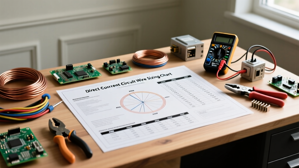
Direct Current Circuit Wire Sizing Reference Chart
The following reference chart is based on copper conductors with 75°C insulation (such as THHN/THWN-2) in an ambient temperature of 30°C (86°F). Ampacity ratings are derived from NEC Table 310.16. Resistance values are approximate for stranded copper at 20°C.
| AWG Size | Max Ampacity (75°C) | Resistance (Ω / 1,000 ft) | Circular Mils (CM) | Recommended Max Run (12V @ 3% Drop) |
|---|---|---|---|---|
| 18 AWG | 14 A | 6.385 | 1,624 | Very short signal runs only |
| 16 AWG | 18 A | 4.016 | 2,583 | Under 5 feet (low draw) |
| 14 AWG | 25 A | 2.525 | 4,107 | Up to 8 feet @ 10A |
| 12 AWG | 30 A | 1.588 | 6,530 | Up to 12 feet @ 15A |
| 10 AWG | 40 A | 0.9989 | 10,380 | Up to 15 feet @ 20A |
| 8 AWG | 55 A | 0.6282 | 16,510 | Up to 20 feet @ 30A |
| 6 AWG | 75 A | 0.3951 | 26,240 | Up to 25 feet @ 40A |
| 4 AWG | 95 A | 0.2485 | 41,740 | Up to 30 feet @ 60A |
| 2 AWG | 130 A | 0.1563 | 66,360 | Up to 40 feet @ 80A |
| 1/0 AWG | 170 A | 0.0983 | 105,600 | Up to 50 feet @ 100A |
| 2/0 AWG | 195 A | 0.0779 | 133,100 | Up to 60 feet @ 120A |
| 4/0 AWG | 260 A | 0.0490 | 211,600 | Up to 80 feet @ 150A |
Note: If bundling more than three current-carrying conductors in a single conduit or raceway, you must apply NEC ampacity derating factors, which will require upsizing your wire.
Real-World DC Applications: Automotive vs. Solar Arrays
The environment in which your direct current circuit operates dictates the insulation type and stranding requirements you must select.
12V Automotive and Marine Environments
In automotive and marine applications, wires are subjected to extreme vibration, heat, and chemical exposure. Standard building wire (THHN) is strictly prohibited here. Instead, you must use SAE J1128 rated wire (such as GXL or TXL), which features thin, tough cross-linked polyethylene (XLPE) insulation that resists abrasion and high engine bay temperatures. For marine environments, UL 1426 marine-grade wire with fine stranding and tinned copper is mandatory to prevent galvanic corrosion and black-wire disease.
48V Solar Photovoltaic (PV) Arrays
Solar arrays operate at high DC voltages (often 150V to 600V DC on the string side) and are exposed to continuous ultraviolet (UV) radiation. Standard insulation will become brittle and crack within a few years when exposed to direct sunlight. According to NFPA 70 (National Electrical Code) Article 690, outdoor solar wiring must utilize PV Wire or USE-2 / XHHW-2 rated conductors. PV Wire features a thicker insulation jacket with built-in UV stabilizers and a 600V or 1000V rating, ensuring long-term survivability on rooftops and ground mounts.
The Danger of DC Arcing and Proper Overcurrent Protection
One of the most misunderstood hazards in electrical work is the behavior of arcs in a direct current circuit. In an AC circuit, the voltage crosses zero 120 times per second (on a 60Hz grid). When a switch or breaker opens under load, this natural zero-crossing helps extinguish the electrical arc that forms between the separating contacts.
DC voltage never crosses zero. When a DC circuit is broken under load, the arc sustains itself, drawing out into a long, incredibly hot plasma channel. This persistent arc can easily melt copper busbars, ignite surrounding insulation, and cause catastrophic fires. Therefore, you must never use standard AC-rated circuit breakers or toggle switches for high-current DC applications.
Always utilize DC-rated overcurrent protection devices (OCPDs). High-quality DC breakers, such as those manufactured by MidNite Solar or Schneider Electric, utilize specialized internal mechanisms like magnetic blowouts (which use a magnetic field to physically stretch and snap the arc) and wider contact gaps to safely extinguish DC arcs. For more on photovoltaic safety and DC arcing, refer to the National Renewable Energy Laboratory (NREL) Photovoltaic Research guidelines.
Expert Troubleshooting Tip: If you are experiencing intermittent thermal runaway or melted terminals in a high-current direct current circuit, do not immediately assume the wire is undersized. In 90% of DIY cases, the failure occurs at the termination point. Soldering large-gauge stranded wire can cause solder to wick up into the insulation, creating a stiff pivot point that eventually fractures under thermal expansion and contraction. Always use properly calibrated ratcheting crimpers with adhesive-lined marine heat shrink for high-amperage DC terminations.
Termination Best Practices for DC Systems
Because DC systems are highly sensitive to resistance, the quality of your terminations is just as important as the wire gauge. A poorly crimped ring terminal introduces micro-ohms of resistance. While negligible in a 5-amp circuit, in a 100-amp inverter cable, that minor resistance will generate immense localized heat (following Joule's First Law, P = I²R).
- Use Ratcheting Crimpers: Never use pliers to crush a terminal. Use a ratcheting crimper calibrated for the specific AWG and terminal type (e.g., hex-crimp for heavy battery cables).
- Adhesive-Lined Heat Shrink: After crimping, apply polyolefin heat shrink with an inner lining of hot-melt adhesive. This creates a waterproof seal that prevents oxygen and moisture from oxidizing the copper strands, which would otherwise increase resistance over time.
- Torque to Spec: Use an inch-pound torque screwdriver or torque wrench when tightening DC busbars and breaker lugs. Undertightening causes arcing; overtightening strips threads and deforms the copper, reducing the contact surface area.
Authoritative Standards and Further Reading
Designing safe and efficient low-voltage systems requires adherence to established electrical codes and physics principles. For a deeper dive into the foundational physics of electron flow and Ohm's Law, the All About Circuits: Direct Current (DC) Fundamentals textbook is an excellent open-source resource. Always consult your local Authority Having Jurisdiction (AHJ) and the latest edition of the NEC before finalizing any permanent DC wiring installation.