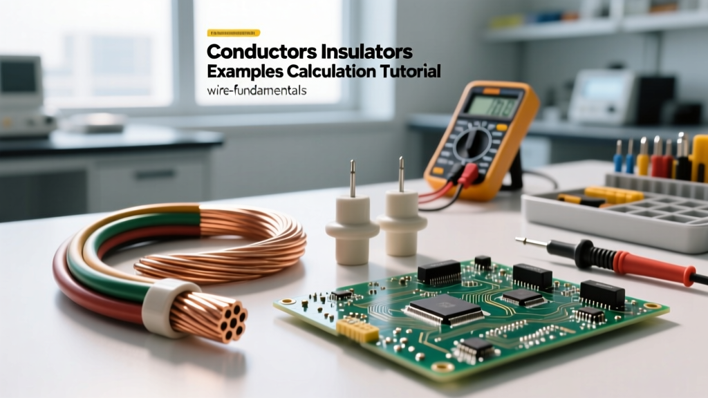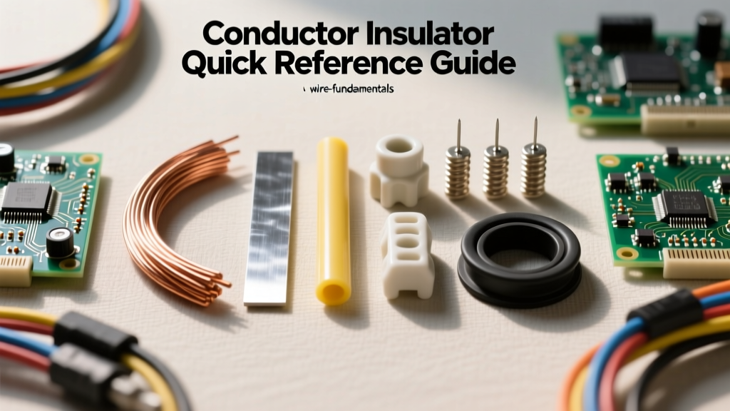

Every electrical circuit, from a simple 5V microcontroller breadboard to a 35kV underground distribution line, relies on the fundamental interplay between two opposing material classes. For electricians, engineers, and DIY electronics enthusiasts, mastering material properties is not just academic; it is the foundation of safe, efficient, and code-compliant system design. This quick reference guide breaks down the physics, practical applications, and failure modes of conductive and insulating materials.
The Core Distinction: Electron Mobility and Band Theory
At the atomic level, the difference between materials that carry current and those that block it comes down to valence electrons and energy band gaps. Conductors possess a 'sea of electrons' in their outermost shell that are loosely bound to the nucleus. When a voltage (electromotive force) is applied, these free electrons drift through the atomic lattice, creating an electrical current. Insulators, conversely, have tightly bound valence electrons and a massive energy band gap, meaning it requires an impractical amount of energy to dislodge an electron and allow current flow.
Defining the Basics: What Is Conductor, Insulator, and Semiconductor?
When apprentices and students ask what is conductor insulator behavior in practical terms, the answer lies in resistivity. A conductor has extremely low electrical resistance (measured in nano-ohm meters). An insulator has exceptionally high resistance, effectively acting as an infinite barrier under normal operating voltages. A semiconductor (like silicon or germanium) sits in the middle; its conductivity can be precisely manipulated through doping or thermal changes, forming the basis of all modern solid-state electronics and microcontrollers.
Quick Reference: Material Properties Chart
The following table provides critical baseline data for common materials encountered in electrical wiring, PCB design, and high-voltage transmission. Data is referenced from standard materials science databases and the HyperPhysics repository at Georgia State University.
| Material | Classification | Resistivity (nΩ·m at 20°C) | Dielectric Strength (kV/mm) | Max Continuous Temp (°C) |
|---|---|---|---|---|
| Silver (Ag) | Conductor | 15.9 | N/A | 961 (Melting) |
| Copper (Cu) | Conductor | 16.8 | N/A | 1084 (Melting) |
| Aluminum (Al) | Conductor | 26.5 | N/A | 660 (Melting) |
| PTFE (Teflon) | Insulator | ~10^18 | 60 - 170 | 260 |
| XLPE | Insulator | ~10^16 | 20 - 50 | 90 (Standard Wire) |
| PVC | Insulator | ~10^15 | 10 - 40 | 75 - 105 |
| Glass | Insulator | ~10^12 | 10 - 40 | 500+ |
Conductor Dynamics in Real-World Wiring
In commercial and residential wiring, copper is the undisputed king. The International Annealed Copper Standard (IACS) sets pure copper's conductivity at 100%. However, understanding conductor behavior requires looking beyond simple DC resistance.
Copper vs. Aluminum: The Weight and Cost Tradeoff
While aluminum possesses only about 61% of the conductivity of copper by volume, it is roughly 70% lighter. This makes aluminum the mandatory choice for overhead transmission lines and large service entrance cables where weight and cost are prohibitive factors. However, aluminum is prone to 'cold creep' (expanding and contracting under thermal load, which loosens terminal screws) and forms a highly resistive oxide layer almost instantly when exposed to air. This necessitates the use of anti-oxidant compounds and CO/ALR-rated terminals in branch circuit wiring.
The Skin Effect in AC Circuits
For high-frequency AC signals or massive power transmission lines, current does not flow evenly through the entire cross-section of the conductor. The 'skin effect' forces the majority of the electron flow to the outer perimeter of the wire. To combat this, high-voltage transmission lines often use ACSR (Aluminum Conductor Steel Reinforced) cables, and RF engineers use silver-plated copper tubing to maximize surface area conductivity while minimizing material costs.
Insulator Dielectric Breakdown and Thermal Limits
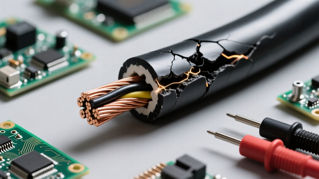
Insulators are not perfect barriers; they are simply materials with a very high threshold for electron displacement. When the voltage gradient across an insulator exceeds its dielectric strength, the material undergoes catastrophic breakdown, tearing electrons from their atomic bonds and creating a conductive plasma channel (an arc or spark).
Wire Insulation Types and NEC Ratings
The National Electrical Code (NEC) strictly categorizes wire insulation based on thermal and environmental limits. Selecting the wrong insulator is a leading cause of electrical fires.
- THHN (Thermoplastic High Heat-resistant Nylon-coated): Rated for 90°C in dry locations and 75°C in wet locations. The nylon jacket provides excellent abrasion resistance, making it ideal for pulling through metal conduits.
- XHHW (Cross-linked Polyethylene High Heat-resistant Water-resistant): Utilizes XLPE insulation. It is more flexible than THHN, has a higher dielectric strength, and handles 90°C in both wet and dry locations. It is the preferred choice for VFD (Variable Frequency Drive) cables due to its ability to withstand high-frequency voltage spikes without corona discharge.
- PTFE (Teflon): Reserved for extreme environments, aerospace, and high-frequency RF applications. It will not melt when touched by a soldering iron, making it indispensable for delicate PCB rework and military-spec wiring harnesses.
Field Tip: When stripping THHN wire, avoid nicking the copper conductor. A nick creates a localized point of high resistance and thermal stress, while simultaneously compromising the dielectric barrier of the insulation, potentially leading to premature short circuits under heavy inductive loads.
Field Failures: When Conductors and Insulators Compromise
Understanding material science is crucial for troubleshooting systemic failures in the field. Most electrical faults are not random; they are the predictable result of material degradation.
Galvanic Corrosion and Dissimilar Metals
When a copper conductor is directly terminated to an aluminum busbar in the presence of an electrolyte (even ambient humidity), a galvanic cell is formed. Aluminum acts as the anode and corrodes rapidly, creating a high-resistance joint. This resistance generates localized heat (I²R losses), which further accelerates oxidation and eventually leads to thermal runaway and fires. Always use bimetallic lugs or appropriate antioxidant pastes when bridging dissimilar conductors.
Insulator Tracking and Corona Discharge
In high-voltage environments, insulators can fail without a complete puncture. 'Corona discharge' occurs when the localized electric field ionizes the surrounding air, creating nitric acid and ozone that chemically degrade the insulator's surface. Over time, this creates microscopic carbonized paths—a phenomenon known as 'dendritic tracking.' Once a track bridges the gap between conductors, a massive flashover occurs. This is why high-voltage ceramic and polymer insulators feature deep 'sheds' or ribs: to increase the surface creepage distance and prevent moisture-dirt tracks from forming a continuous conductive path.
Semiconductors: The Bridge in Modern Electronics
While wire fundamentals focus on macro-scale conductors and insulators, the microcontroller revolution relies on semiconductors. Materials like Silicon (Si) and Gallium Nitride (GaN) have band gaps that can be engineered. By 'doping' silicon with elements like phosphorus (creating N-type material with extra electrons) or boron (creating P-type material with 'holes'), engineers construct diodes, MOSFETs, and IGBTs. These components act as electrically controlled switches, allowing a 5V logic signal from a microcontroller to safely switch a 240V AC inductive load via a solid-state relay, entirely isolating the low-voltage control circuit from the high-voltage power circuit.
Summary and Safety Standards
The dichotomy of conductors and insulators dictates every rule in electrical safety. Conductors are chosen for their low resistivity, thermal capacity, and mechanical flexibility. Insulators are chosen for their dielectric strength, thermal stability, and chemical resistance. For authoritative data on material testing, standardization, and safety limits, professionals routinely consult resources provided by the National Institute of Standards and Technology (NIST) and the NFPA. Whether you are sizing a 12 AWG ground conductor for a residential branch circuit or designing a high-speed digital bus, respecting the physical limits of your materials is the hallmark of expert-level electrical engineering.