
The Anatomy of the Circuit Symbol for Potentiometer
When designing analog circuits, audio interfaces, or user-control panels, the potentiometer remains an indispensable electromechanical component. However, a surprising number of PCB layout errors and schematic misinterpretations stem from a fundamental misunderstanding of the circuit symbol for potentiometer and how it translates to physical manufacturer datasheets. As a senior design engineer, I frequently review schematics where the symbolic representation of a three-terminal variable resistor is treated as an abstract concept rather than a direct map to a physical footprint.
In this datasheet breakdown, we will dissect the standard schematic symbols, decode the international standard wars (IEC vs. IEEE), and map these symbols directly to the physical pinouts and taper graphs found in industry-standard datasheets like the Bourns 3296W trimpot and the ALPS RK09K audio potentiometer.
IEC 60617 vs. IEEE 315: Decoding the Standard Wars
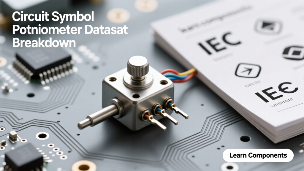
Before you can accurately interpret a datasheet, you must understand the schematic language being used. The circuit symbol for potentiometer varies depending on the regional and organizational standards adopted by the CAD library or the design engineer.
The IEEE 315 (ANSI) Standard
Prevalent in North America and older legacy designs, the IEEE 315 standard represents a fixed resistor as a zigzag line. Consequently, the circuit symbol for potentiometer under this standard is a zigzag line intersected by an arrow pointing inward. The arrow represents the wiper (the movable contact), while the two ends of the zigzag represent the fixed resistive track terminals.
The IEC 60617 Standard
In Europe and most modern international datasheets (including those from Vishay and TT Electronics), the IEC 60617 standard is dominant. Here, a fixed resistor is depicted as a simple rectangle. The IEC circuit symbol for potentiometer is therefore a rectangle with an arrow pointing toward the center of one of the long sides.
Information Gain: When importing SPICE models or CAD footprints from international suppliers, ensure your schematic capture software is set to the correct symbol library. Mixing IEC rectangular resistors with IEEE zigzag potentiometers in the same schematic creates visual clutter and increases the risk of netlist errors during design rule checks (DRC).
Datasheet Breakdown: Mapping Symbols to Physical Pinouts
The most critical failure point in prototyping occurs when the schematic symbol is incorrectly mapped to the physical component footprint. Let us break down the Bourns 3296W Datasheet, one of the most ubiquitous 3/8-inch square cermet trimpots used in calibration circuits.
In a standard schematic, the terminals are labeled 1, 2, and 3. But how does this map to the physical top-down view of the Bourns 3296W?
| Schematic Symbol Terminal | Electrical Function | Bourns 3296W Physical Pin | Rotation State (Standard) |
|---|---|---|---|
| Terminal 1 | CCW (Counter-Clockwise) End | Pin 1 (Left) | Minimum Resistance to Wiper |
| Terminal 2 | Wiper (Movable Contact) | Pin 2 (Center) | Variable Output |
| Terminal 3 | CW (Clockwise) End | Pin 3 (Right) | Maximum Resistance to Wiper |
Expert Troubleshooting Tip: Datasheets explicitly define the pinout based on a specific mechanical orientation. For the Bourns 3296W, the datasheet specifies the pinout when viewing the component from the top with the adjustment screw facing you. If you are designing a PCB where the trimpot will be mounted on the bottom layer or viewed from the solder side, your physical footprint must mirror the pinout to match the schematic symbol, otherwise, your calibration logic will be inverted.
Taper Representations: Linear, Audio, and Anti-Log
The basic circuit symbol for potentiometer does not inherently convey the taper—the mathematical relationship between the shaft's mechanical rotation and the resistance change. This is where the datasheet becomes your primary source of truth.
Decoding Manufacturer Taper Codes
Manufacturers use alphanumeric codes stamped on the component casing and detailed in the datasheet's ordering information.
- B Taper (Linear): Resistance changes at a constant rate. A 50% shaft rotation yields 50% of the total resistance. Used in voltage dividers and position sensors.
- A Taper (Audio/Logarithmic): Resistance changes exponentially. Used in audio amplifiers to match the human ear's logarithmic perception of loudness.
- C Taper (Reverse Log/Anti-Log): The inverse of the audio taper, often used in specific analog synth filter cutoff circuits.
Real-World Example: ALPS RK09K Audio Taper
When reviewing the datasheet for an audio-grade component like the ALPS RK09K series, you will find a 'Resistance Taper Curve' graph. This graph plots the percentage of total resistance against the percentage of mechanical travel. An 'A' taper pot will show a shallow curve at the beginning of the rotation and a steep curve at the end. While the schematic symbol remains identical regardless of taper, the application circuit must account for this. Wiring an audio taper pot backward (swapping Terminal 1 and Terminal 3 in the layout) will result in a volume knob that does nothing for 80% of its rotation and then violently spikes in volume—a classic mistake caught only by cross-referencing the schematic symbol with the datasheet's taper graph.
Rheostat vs. Voltage Divider: Symbol Variations
A common schematic error is using the standard three-terminal potentiometer symbol when the component is actually being wired as a two-terminal variable resistor (rheostat). According to the All About Circuits reference guide on potentiometers, the symbol must accurately reflect the electrical configuration to aid in troubleshooting.
The Rheostat Configuration
When using a potentiometer to vary current (such as dimming an LED or setting a bias current), only two terminals are used. The correct circuit symbol for a potentiometer wired as a rheostat shows the wiper arrow tied directly to one of the fixed terminals.
Datasheet Warning: If you wire a cermet trimpot as a rheostat by simply leaving Terminal 3 floating, you risk an open-circuit failure if the wiper experiences micro-vibrations and momentarily loses contact with the resistive track. By tying the wiper (Terminal 2) to Terminal 3 in your schematic and PCB layout, the maximum resistance is bounded by the total track resistance, preventing the node from floating to a high-impedance, unpredictable state. Always reflect this wiper-tie in your schematic symbol.
Mechanical vs. Electrical Limits: The Hidden Datasheet Specs
The schematic symbol implies that the wiper can travel seamlessly from 0% to 100% of the resistive track. Physical datasheets tell a more restrictive story.
Take a standard 9mm rotary potentiometer. The datasheet will list two distinct angles:
- Mechanical Angle: Typically 300°. This is the physical hard-stop of the internal metal collar.
- Electrical Angle: Typically 280° ± 5°.
This 20-degree discrepancy means that for the first and last 10 degrees of physical knob rotation, the wiper is resting on the conductive end-tracks, which have virtually zero resistance. If your microcontroller's ADC is reading the wiper voltage, the digital values will hard-clip at 0 and 1023 (for a 10-bit ADC) before the user actually reaches the physical end-stops of the knob. Designing your software scaling and physical knob caps requires acknowledging this delta, which is entirely invisible in the standard circuit symbol but explicitly detailed in the component's mechanical drawing.
Summary Checklist for PCB Layout
To ensure your schematic symbols translate flawlessly into manufactured PCBs, use this pre-layout checklist:
- Verify Standard: Confirm if your schematic uses IEC (rectangle) or IEEE (zigzag) symbols and ensure your CAD footprint matches the terminal numbering logic.
- Check Wiper Tie: If using the pot as a rheostat, ensure the schematic symbol shows the wiper tied to a fixed terminal, and route the PCB traces accordingly to prevent floating nodes.
- Validate Pinout Orientation: Cross-reference the datasheet's mechanical drawing with your footprint. Does 'Pin 1' on your screen match 'Pin 1' on the physical silkscreen when viewed from the correct side?
- Account for Taper: Ensure the BOM specifies the correct taper code (A, B, or C) and that the schematic notes reflect the intended application (audio vs. linear sensing).
- Review Wiper Resistance: For precision analog circuits, check the datasheet for 'Wiper Contact Resistance' (often 1Ω to 5Ω). The ideal schematic symbol assumes 0Ω, which can introduce gain errors in high-impedance op-amp feedback loops.
By treating the circuit symbol for potentiometer not just as a generic drawing, but as a direct, interrogable link to the manufacturer's datasheet, you eliminate entire categories of prototyping errors and ensure robust, predictable analog designs.