
Phase 1: Building the Foundation — Understanding Voltage Architecture
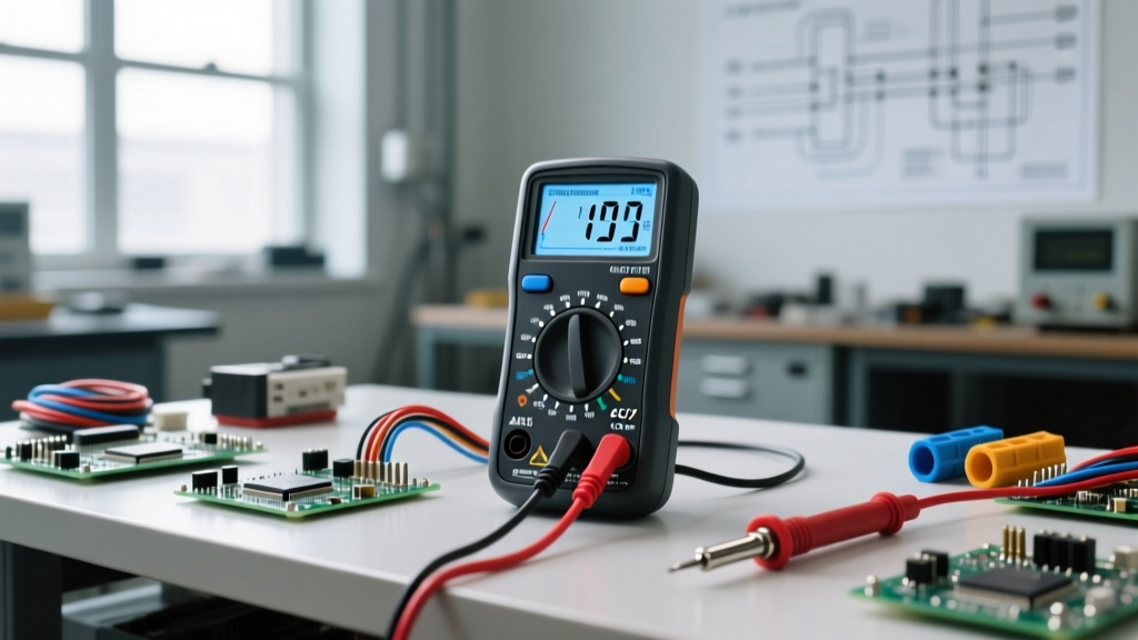
Learning how to check voltage using a multimeter is the cornerstone of electrical diagnostics. Before you touch a single probe to a live circuit, you must understand the fundamental architecture of your digital multimeter (DMM). Voltage is the electrical potential difference between two points, and your meter acts as a high-resistance bridge to measure that potential without altering the circuit's behavior.
AC vs. DC: Selecting the Right Domain
The most critical mistake beginners make is selecting the wrong voltage domain. Direct Current (DC), denoted by a solid and dashed line (V⎓), flows unidirectionally and is standard in batteries, solar panels, and microcontroller logic boards. Alternating Current (AC), denoted by a wavy line (V~), reverses direction periodically and is used in mains power and HVAC systems. Applying a DC setting to an AC circuit will usually result in a reading of zero or erratic fluctuations, while applying an AC setting to a DC circuit will yield similarly useless data.
True-RMS vs. Average-Responding Meters
As you advance your skills, you must understand the difference between True-RMS (Root Mean Square) and average-responding meters. Budget meters calculate AC voltage by assuming a perfect sine wave. However, modern electronics like LED drivers, variable frequency drives (VFDs), and dimmer switches create distorted, non-linear waveforms. A True-RMS meter, such as the Brymen BM235 or Fluke 87V, samples the actual waveform and calculates the true heating value of the voltage. According to Fluke's technical documentation on True-RMS, using an average-responding meter on a non-linear load can result in measurement errors of up to 40%, leading to severe misdiagnoses.
Phase 2: Execution — The Core Mechanics of Probing
Proper physical technique separates amateurs from seasoned electrical technicians. The goal is to achieve a solid connection while minimizing the risk of arc flashes or short circuits.
Lead Placement and Dial Configuration
Your black probe must always be inserted into the COM (Common) jack. The red probe must be inserted into the VΩ (Volts/Ohms) jack. Never leave the red probe in the Amps (A or mA) jack when measuring voltage. The Amps jack contains a low-resistance shunt; inserting it into a voltage source creates a dead short, which will instantly blow the meter's internal fuse or cause a catastrophic arc flash.
The 'One-Hand Rule' for High-Voltage Safety
When probing live mains panels or receptacles above 50V, adopt the 'One-Hand Rule'. Keep your non-dominant hand in your pocket or firmly behind your back. If you accidentally touch a live conductor with your left hand while your right hand holds the grounded probe, current will travel across your chest cavity. The threshold for ventricular fibrillation is remarkably low—roughly 30 to 50 milliamps of AC current. By keeping one hand isolated, you prevent current from crossing the heart. For comprehensive workplace safety protocols, refer to the OSHA guidelines on protecting electrical workers.
Phase 3: Application — Real-World Scenarios and Measurement Data
To build diagnostic intuition, you need to know what 'normal' looks like. The table below outlines expected voltage readings for common household, automotive, and electronics scenarios. Understanding the acceptable tolerance ranges is crucial for determining if a circuit is healthy or failing.
| Circuit Type | Meter Setting | Nominal Voltage | Acceptable Tolerance Range | Common Failure Indicators |
|---|---|---|---|---|
| US Standard Receptacle | V~ (AC) | 120V | 114V - 126V | Readings below 110V indicate voltage drop from undersized wiring or loose neutral connections. |
| USB-C / 5V Logic Rail | V⎓ (DC) | 5.0V | 4.75V - 5.25V | Readings under 4.5V usually point to a failing voltage regulator or excessive parasitic draw. |
| 12V Automotive Battery | V⎓ (DC) | 12.6V (Resting) | 12.4V - 12.8V | A resting voltage of 11.9V or lower indicates a sulfated or dead cell. |
| Alternator Output (Running) | V⎓ (DC) | 14.2V | 13.7V - 14.7V | Readings above 15V suggest a failed voltage regulator, risking ECU damage. |
| 240V Dryer/Range Outlet | V~ (AC) | 240V | 228V - 252V | Measuring 120V across the two hot legs indicates a tripped double-pole breaker or lost phase. |
Phase 4: Mastery — Advanced Troubleshooting and Ghost Voltages
As you encounter more complex wiring environments, you will inevitably face 'ghost voltages.' This phenomenon occurs when a high-impedance digital multimeter (typically featuring a 10 Megohm input impedance) picks up capacitively coupled voltage from adjacent live wires.
Identifying Phantom Voltage
Imagine you are testing a 14 AWG wire in a conduit that runs parallel to a live 120V circuit for 50 feet. The dead wire acts as one plate of a capacitor, and the live wire acts as the other. Your 10 Megohm DMM will display a phantom reading of anywhere from 40V to 90V, leading you to falsely believe the circuit is energized.
Utilizing Low-Impedance (LoZ) Mode
To solve this, advanced meters like the Fluke 117 feature a LoZ (Low Impedance) mode. Engaging LoZ drops the meter's internal input impedance from 10 Megohms down to approximately 3 kilohms. This creates a small load that safely bleeds off the capacitive ghost charge, causing the phantom voltage to drop to a true 0V, while legitimate hard-wired voltages remain unaffected. Mastering the use of LoZ is a definitive milestone in the skill-building path of an electrical diagnostician. For deeper insights into measurement anomalies, Electronics Notes provides an excellent breakdown of multimeter voltage measurement principles.
Phase 5: Preservation — Safety Protocols and Preventing Meter Damage
Your multimeter is a precision instrument, but it is also your primary shield against electrical hazards. Preserving your equipment and your physical safety requires strict adherence to Category (CAT) ratings and fuse integrity.
Decoding CAT Ratings
Never use a CAT II rated meter to measure outdoor mains or service entrance panels. CAT ratings define the meter's ability to withstand transient voltage spikes (surges) specific to different environments. A CAT III 600V meter is designed to handle the impedance of branch circuits and distribution panels, while a CAT IV 600V meter is required for service entrances and utility connections where the available fault current is massive. The numbers on the meter represent the steady-state voltage, but the CAT rating dictates the surge survival threshold.
The Role of HRC Fuses
High-quality multimeters utilize High Rupturing Capacity (HRC) fuses filled with sand. If you accidentally measure voltage with the leads in the current jacks, the resulting short circuit can generate thousands of amps of fault current in milliseconds. An HRC fuse will vaporize its internal element and contain the resulting plasma and arc blast inside the ceramic body. Cheap, uncertified meters often use standard glass fuses that will shatter under these conditions, turning the meter into a fragmentation grenade in your hand. Always verify that your meter's HRC fuses are intact and rated specifically for your DMM model before tackling high-energy industrial panels.
Pro Tip: Make it a habit to perform a 'Live-Dead-Live' test. Before checking your target circuit, test your meter on a known live source (like a standard outlet). Then, test your target circuit. Finally, test the known live source again. This guarantees your meter didn't suffer a blown internal fuse or dead battery between the first and second readings, ensuring your 'dead' reading is genuinely safe to touch.
By progressing through these phases—from understanding True-RMS architecture to mastering LoZ troubleshooting and respecting HRC safety protocols—you transition from simply reading a screen to truly diagnosing electrical systems with confidence and precision.