
The Anatomy of a Standard 830-Point Solderless Board
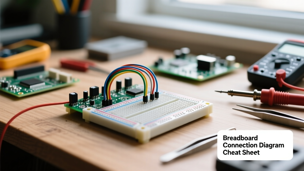
Before routing a single wire, understanding the physical and electrical anatomy of your prototyping surface is critical. The industry-standard 830-point solderless breadboard (commonly manufactured by brands like Elegoo, Global Specialties, and Bus Pirate) is divided into distinct functional zones. The board features 630 terminal strip tie-points for component placement and 200 power rail tie-points for voltage distribution. The entire grid is based on a 0.1-inch (2.54mm) pitch, perfectly aligning with the pin spacing of standard Dual In-Line Package (DIP) integrated circuits.
Internal Wiring Matrix: Node-to-Node Connectivity Map
The most common mistake beginners make is assuming every hole is an isolated node or that the entire row is connected. A breadboard connection diagram reveals a highly specific internal clipping structure. Beneath the plastic ABS housing lie phosphor bronze metal clips that grip inserted wires.
| Zone | Internal Connectivity Pattern | Primary Use Case |
|---|---|---|
| Terminal Strips (A-E) | Rows of 5 holes are electrically connected horizontally. | DIP IC legs, resistor/capacitor networks, transistor biasing. |
| Terminal Strips (F-J) | Rows of 5 holes are electrically connected horizontally. | DIP IC legs, secondary component routing. |
| Center Divider (Ditch) | Physical and electrical gap (0.3 inches wide). | Isolates Row E from Row F to prevent IC pin shorting. |
| Power Rails (Top/Bottom) | Columns of 50 holes connected vertically (usually marked with +/- or Red/Blue lines). | Distributing VCC, VDD, GND, and analog reference voltages. |
For a comprehensive visual breakdown of these internal metal clips, SparkFun's Breadboard Tutorial provides excellent x-ray photography of the internal leaf-spring mechanisms.
Wire Gauge & Contact Pressure Specifications
The internal phosphor bronze clips are engineered for specific wire diameters. Using the wrong wire gauge is the leading cause of intermittent connections and physical damage to the breadboard's internal contacts. Stranded wire is strictly prohibited as it frays, bends, and leaves copper splinters inside the clips.
| Wire Gauge (AWG) | Diameter (mm) | Compatibility & Contact Quality |
|---|---|---|
| 22 AWG (Solid) | 0.644 mm | Ideal. Provides optimal friction and gas-tight contact pressure. |
| 24 AWG (Solid) | 0.511 mm | Good. Slightly looser fit; reliable for most digital logic circuits. |
| 26 AWG (Solid) | 0.405 mm | Marginal. Risk of poor contact resistance; avoid for power rails. |
| 28+ AWG / Stranded | < 0.321 mm | Failure. Will not engage the clip properly; causes open circuits. |
The Hidden Diagram: Parasitic Capacitance & Resistance
A breadboard connection diagram on paper shows ideal, zero-resistance wires. In reality, a solderless board introduces significant parasitic elements that can destroy high-frequency or precision analog circuits. According to high-frequency design principles discussed on All About Circuits, adjacent rows on a standard breadboard exhibit 2pF to 5pF of parasitic capacitance.
High-Frequency Limits
While 5pF is negligible for a 1kHz audio filter or a simple 555 timer astable circuit, it creates an unintended low-pass filter in RF or high-speed digital circuits. At 10MHz, a 5pF capacitor presents an impedance of roughly 3.18kΩ. If you are routing a high-impedance analog sensor signal next to a 5V PWM clock line, capacitive coupling will inject severe noise into your ADC readings. As a general rule, breadboards should be avoided for signals exceeding 10MHz or for circuits requiring microvolt-level precision.
Bridging and Bussing Techniques for Complex ICs
When designing a breadboard connection diagram for complex microcontrollers (like an ATmega328P or a 40-pin DIP), you will quickly run out of adjacent tie-points. Mastering the 'bus' technique is essential.
- Power Bussing: Always run VCC and GND along the entire length of the power rails. On older or specific military-spec breadboards, the power rails are split in the exact middle. You must use a jumper wire to bridge the center gap, or half your board will be unpowered.
- Signal Bussing: Use the terminal strips as vertical buses. Run a 22 AWG solid wire down column 'A' to act as a local ground or signal bus, then use shorter jumper wires to branch off to specific components.
- Decoupling Placement: Place 100nF ceramic decoupling capacitors as physically close to the IC's VCC and GND pins as possible, utilizing the same 5-hole row to minimize trace inductance.
Expert Prototyping Tip: Never route a high-current load (like a motor or a high-power LED array) through the breadboard's internal clips. The thin phosphor bronze metal cannot safely handle currents above 1A without overheating, melting the ABS plastic, and creating a fire hazard. Use the breadboard only for the logic-level control signals (e.g., driving a MOSFET gate), and wire the high-current path directly on a perfboard or terminal block.
Troubleshooting Matrix: When the Physical Diagram Fails
Even with a perfect schematic, physical breadboard connections degrade. Here is how to diagnose the most common failure modes:
- Oxidized Clips: If a board is stored in a humid environment, the tin-plated clips oxidize. This increases contact resistance. Fix: Insert and remove a thick 20 AWG wire 4-5 times into the faulty hole to mechanically scrape away the oxidation layer.
- Over-Spread Clips: Forcing thick component leads (like heavy power diodes or potentiometers) into the holes permanently bends the leaf springs, ruining the clip for standard 22 AWG wires. Fix: Solder standard 22 AWG extension wires to thick component leads before inserting them into the board.
- The Split-Rail Trap: Assuming the red and blue lines on opposite sides of the board are connected. They are entirely isolated. You must manually jumper the left and right power rails if your circuit spans across the center ditch.
The Multimeter Continuity Trap
Most digital multimeters (like the Fluke 117 or Brymen BM235) trigger their continuity beeper at anything below 30Ω. However, a degraded breadboard clip might exhibit 15Ω of contact resistance. It will pass the beep test, but if your microcontroller draws 100mA, Ohm's Law (V = IR) dictates a 1.5V drop across that single connection. Your 3.3V logic rail will arrive at the IC as 1.8V, causing brownouts, random resets, and erratic I2C bus failures. Always measure actual voltage under load at the IC pin, not just continuity at the power rail.