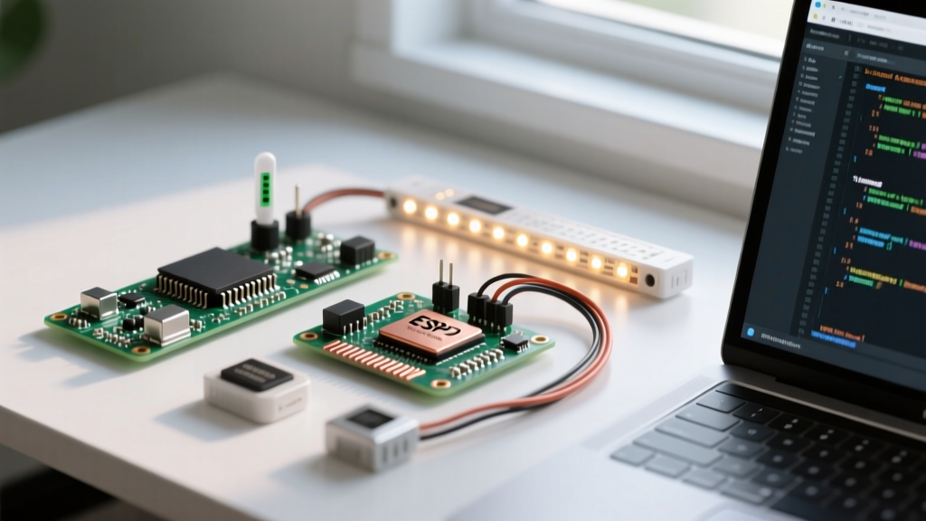

The RF Module Landscape: Choosing the Right Frequency
When integrating wireless communication into microcontroller projects, selecting the correct RF module is the difference between a reliable IoT network and a debugging nightmare. The term 'module RF' encompasses a vast array of transceivers operating across different ISM (Industrial, Scientific, and Medical) bands. For DIY electronics makers, robotics enthusiasts, and home automation engineers, the decision usually boils down to three primary frequency categories: 2.4 GHz for high-speed local data, Sub-1 GHz (433/868/915 MHz) for long-range penetration, and specialized protocols like LoRa for extreme-distance, low-power telemetry.
In this comprehensive tool review and buyer's guide, we dissect the three most dominant RF modules on the maker market. We will evaluate their silicon architectures, real-world failure modes, SPI bus requirements, and antenna matching nuances to help you choose the exact component for your next Arduino, ESP32, or Raspberry Pi Pico build.
Deep-Dive Reviews: Top 3 RF Modules for Makers
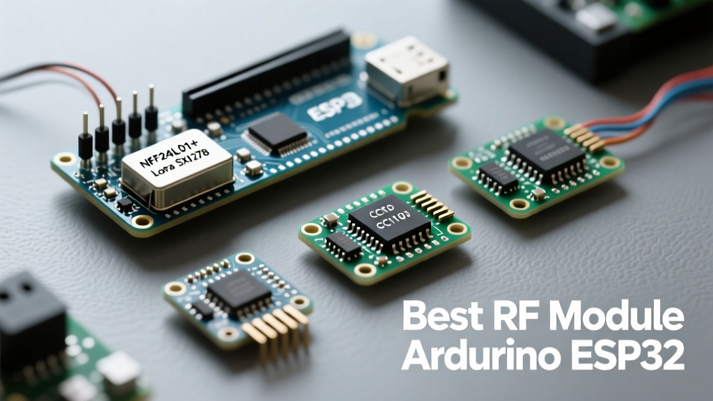
1. nRF24L01+PA+LNA: The High-Speed 2.4GHz Workhorse
The Nordic Semiconductor nRF24L01+ is arguably the most ubiquitous 2.4 GHz transceiver in the DIY space. While the base PCB-trace antenna version is limited to roughly 30 feet indoors, the PA+LNA (Power Amplifier + Low Noise Amplifier) variant with an external SMA antenna can achieve line-of-sight ranges exceeding 800 meters. It utilizes an enhanced ShockBurst protocol, handling automatic packet handling, CRC, and auto-retransmission natively in silicon.
Technical Specifications & Integration:
- Interface: SPI (Mode 0, max 10 MHz clock speed).
- Logic Levels: 3.3V only. The inputs are strictly NOT 5V tolerant.
- Throughput: Up to 2 Mbps, making it ideal for streaming sensor arrays or low-latency RC telemetry.
- Library: The
RF24library by TMRh20 is the gold standard for Arduino/C++ environments.
Real-World Failure Mode: The most common issue makers face with cheap clone nRF24L01+ modules is VCC ripple during transmission bursts. The PA+LNA versions can draw up to 115 mA during peak TX, which easily collapses the 3.3V rail on standard Arduino Uno linear regulators. Hardware Fix: Always solder a 10µF to 47µF electrolytic capacitor directly across the VCC and GND pins of the module to stabilize the voltage droop.
2. Semtech SX1278 LoRa: The Long-Range IoT Champion
If your project requires sending small packets of telemetry data over several kilometers, LoRa (Long Range) is the undisputed king. The Semtech SX1278 utilizes Chirp Spread Spectrum (CSS) modulation, allowing the receiver to decode signals up to 20 dB below the noise floor. This results in an astonishing link budget of up to 168 dB.
Technical Specifications & Integration:
- Frequencies: 433 MHz (EU/Asia) or 915 MHz (Americas). Note: Using 433 MHz in the US or 915 MHz in Europe violates local RF spectrum laws.
- Interface: SPI with additional DIO (Digital I/O) pins for interrupt-driven packet reception.
- Throughput: Very low (typically 0.3 kbps to 37.5 kbps). Do not use this for audio or high-frequency polling.
- Library: Sandeep Mistry's
LoRa.hor theRadioLibrepository.
Real-World Failure Mode: SPI bus contention. Because LoRa modules rely on precise timing for frequency hopping and CAD (Channel Activity Detection), sharing the SPI bus with high-speed devices like SD cards or TFT displays can cause missed DIO0 interrupts. Always use a dedicated hardware SPI bus or ensure your software polls the interrupt pin with microsecond precision.
3. TI CC1101: The Sub-GHz Reverse Engineering Tool
The Texas Instruments CC1101 is a highly configurable Sub-1 GHz transceiver. Unlike the nRF24L01+ which uses a proprietary protocol, the CC1101 is a raw modulator/demodulator. It supports OOK (On-Off Keying), ASK, FSK, and MSK. This makes it the ultimate tool for makers looking to interface with legacy 433 MHz home automation devices, wireless weather stations, or RF-controlled relays.
Technical Specifications & Integration:
- Frequencies: 300-348 MHz, 387-464 MHz, and 800-928 MHz.
- Configuration: Requires programming over 50 internal registers. TI's SmartRF Studio software is essential for calculating the correct baud rate and deviation registers before porting them to your microcontroller code.
- Library:
RadioLiborSmartRC-CC1101-Driver-Lib.
Expert Tip: The CC1101 requires a highly stable 26 MHz crystal oscillator. If you purchase ultra-cheap breakout boards with poorly calibrated crystals, your frequency drift will cause packet loss at the edges of the ISM bands. Invest in modules from reputable RF board manufacturers like Elecrow or DFRobot.
Comparative Breakdown: Range, Power, and Protocol
Below is a structured comparison to help you map the right module RF specifications to your project constraints.
| Feature | nRF24L01+ (PA+LNA) | SX1278 (LoRa) | CC1101 (Sub-GHz) |
|---|---|---|---|
| Frequency Band | 2.4 GHz (Global) | 433 / 868 / 915 MHz | 315 / 433 / 868 / 915 MHz |
| Max Data Rate | 2 Mbps | 37.5 kbps | 500 kbps |
| Typical Urban Range | 100 - 300 meters | 2 - 5 kilometers | 300 - 800 meters |
| Wall Penetration | Poor (absorbed by water/concrete) | Excellent | Good |
| Primary Use Case | RC cars, drone telemetry, local mesh | Agricultural IoT, remote weather stations | Smart home bridges, RF sniffing |
| Approx. Cost (USD) | $4.00 - $7.00 | $6.00 - $10.00 | $3.50 - $6.00 |
Real-World Hardware Debugging: Beyond the Code
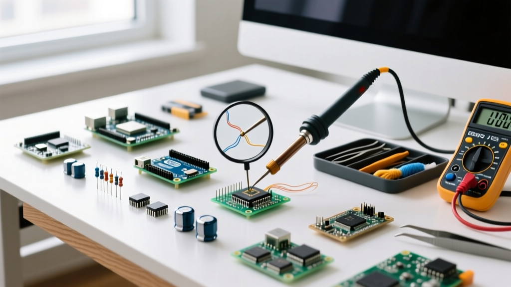
When an RF module fails to initialize or drops packets, 90% of maker forums will blame the code. In reality, RF engineering is an analog discipline masked by digital interfaces. Here are the top hardware-level debugging steps for RF modules:
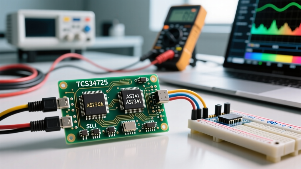
- Verify SPI Wiring with a Logic Analyzer: The CSN (Chip Select Not) and CE (Chip Enable) pins on the nRF24L01+ are frequently confused. CE controls the TX/RX state machine, while CSN gates the SPI data. If your module returns
0xFFor0x00on initialization, your MISO/MOSI lines are either swapped or the SPI clock is exceeding the module's maximum rating. - Check the VSWR (Voltage Standing Wave Ratio): Transmitting without an antenna attached will reflect RF energy back into the silicon, permanently frying the PA (Power Amplifier) stage. Never power on an RF module without an antenna securely fastened.
- Ground Plane Proximity: Mounting a 433 MHz quarter-wave whip antenna too close to a large copper ground plane (like the underside of an Arduino Mega) will detune the resonant frequency. Keep the antenna element at least 2 inches away from any horizontal copper pours.
Antenna Selection and Impedance Matching
The best silicon in the world is useless with a poorly matched antenna. Most DIY RF modules feature a 50-ohm SMA or u.FL connector. For 2.4 GHz modules (nRF24L01+), a standard 1/4 wave dipole or a PCB patch antenna tuned to 2.45 GHz is sufficient. However, for Sub-1 GHz modules (LoRa and CC1101), the physical length of the antenna is critical.
The formula for a quarter-wave antenna is Length (meters) = 71.25 / Frequency (MHz). For a 433 MHz LoRa module, your antenna element should be exactly 16.4 cm long. Using a generic 'spring' coil antenna often found on cheap remotes will result in a severe impedance mismatch, dropping your effective radiated power (ERP) by up to 60%. Always invest in a tuned fiberglass or rubber duck antenna rated specifically for your module's operating frequency.
Final Recommendations for Your Workbench
If you are building high-speed, short-range robotics or wireless game controllers, stock your lab with nRF24L01+PA+LNA modules and a bulk pack of 10µF capacitors. For off-grid environmental monitoring, solar-powered telemetry, or multi-acre farm automation, the SX1278 LoRa module is non-negotiable. Finally, if you are researching legacy RF protocols, building universal remotes, or bridging older 433 MHz sensors to a modern MQTT broker, the CC1101 provides the raw register-level access required for deep signal analysis. By matching the physics of the frequency band to your project's payload requirements, you eliminate wireless instability at the hardware level.