
The Hidden Power Drain in ESP8266 Projects
When engineers and hobbyists transition from USB-powered prototypes to battery-operated IoT deployments, the ESP8266 often presents a harsh reality check. A standard NodeMCU v3 development board, left in its default idle state, will drain a 2000mAh 18650 lithium-ion battery in less than two weeks. This is not because the ESP8266 chip itself is inherently power-hungry, but because the peripheral components on standard development boards completely undermine the silicon's low-power capabilities.
Designing truly energy-efficient ESP8266 projects requires a fundamental shift in how you approach both hardware selection and software architecture. You must move away from continuous polling and embrace asynchronous event-driven designs, microamp-level quiescent current management, and aggressive sleep states. In this guide, we will dissect the exact hardware modifications, sleep mode configurations, and software strategies required to extend the battery life of your ESP8266 IoT nodes from weeks to multiple years.
Decoding Sleep Modes for Maximum Battery Life
The ESP8266 silicon features three distinct power-saving modes. Understanding the exact current draw and wake-up latency of each is critical for sizing your battery and solar harvesting circuits. According to the official Espressif ESP8266EX Datasheet, the power states are defined as follows:
| Sleep Mode | Wi-Fi Radio | CPU State | Typical Current | Wake-Up Source |
|---|---|---|---|---|
| Modem Sleep | Off (between DTIM beacons) | Running | ~15 mA | Automatic (DTIM interval) |
| Light Sleep | Off | Suspended | ~0.5 mA | GPIO Interrupt, Wi-Fi |
| Deep Sleep | Off | Off (RTC active) | ~20 µA | Timer, External Reset (D0 to RST) |
Why Deep Sleep is the Only Viable Option for Battery Nodes
For remote environmental sensors—such as soil moisture monitors or weather stations—Deep Sleep is mandatory. In Deep Sleep, the ESP8266 shuts down the CPU, RAM, and Wi-Fi radio entirely. Only the Real-Time Clock (RTC) and a small 512-byte RTC memory block remain powered to keep the timer alive. The chip draws approximately 20 microamps (µA). However, achieving this 20 µA figure in the real world requires stripping away the parasitic drain of development board peripherals.
Hardware Modifications for Microamp Quiescent Current
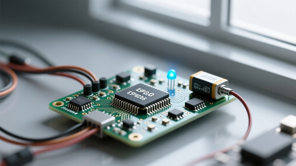
If you wire a bare ESP-12F module directly to a 3.3V LiFePO4 battery, you can achieve near-datasheet deep sleep currents. However, if you use a NodeMCU or Wemos D1 Mini, you must address the onboard voltage regulators and indicator LEDs.
The AMS1117 Voltage Regulator Problem
Most NodeMCU boards utilize the AMS1117-3.3 linear voltage regulator to step down 5V USB power to 3.3V. While cheap, the AMS1117 has a quiescent current of roughly 5mA to 10mA. Even if the ESP8266 is in deep sleep drawing 20µA, the AMS1117 will continuously bleed 5,000µA from your battery.
Pro-Tip: For custom PCB designs in your ESP8266 projects, replace the AMS1117 with an ultra-low quiescent current LDO like the Microchip MCP1700 or the Texas Instruments TPS782. These regulators draw less than 5µA of quiescent current, aligning perfectly with the ESP8266's deep sleep profile.
Desoldering LEDs and USB-UART Bridges
The onboard power LED on a Wemos D1 Mini draws roughly 3mA to 5mA. Furthermore, the CP2102 or CH340G USB-to-UART bridge chips remain active when powered via the 3.3V pin, leaking current back through their I/O protection diodes. For a production-grade battery node, you must physically desolder the power LED and, ideally, design your PCB without an onboard USB-UART chip, relying instead on an external FTDI programmer for occasional firmware updates.
Software Strategies: Polling, MQTT, and Fast Connect
Hardware optimization only gets you halfway. The remaining battery drain occurs during the active window—the time between the ESP8266 waking up and returning to sleep. Minimizing this active window is the core of energy-efficient firmware design.
Optimizing Wi-Fi Connection Time via RTC Memory
By default, when the ESP8266 wakes from deep sleep and calls WiFi.begin(ssid, password), it performs a full RF scan of the 2.4GHz spectrum to locate the access point. This scanning process keeps the power-hungry RF radio active for 2 to 5 seconds, drawing ~70mA.
To bypass this, you can save the Wi-Fi channel and BSSID (MAC address) of your router into the ESP8266's RTC memory before entering deep sleep. Upon waking, you pass these specific parameters to WiFi.begin(). The Arduino ESP8266 Core Documentation details how RTC memory persists across deep sleep resets. By forcing the radio to connect directly to a known BSSID on a known channel, you can reduce the Wi-Fi connection time from 4 seconds down to roughly 400 milliseconds.
Sensor Power Gating
Never wire your sensors directly to the continuous 3.3V rail. Sensors like the BME280 or capacitive soil moisture probes draw idle current even when not actively taking a reading. Instead, power your sensors via a GPIO pin or a small P-channel MOSFET controlled by the ESP8266. Turn the sensor power on, wait for the sensor's internal capacitors to stabilize (usually 10-50ms), take the reading via I2C/SPI, and immediately cut the power before initiating the Wi-Fi connection.
Real-World Power Budget: A Soil Moisture Sensor Case Study
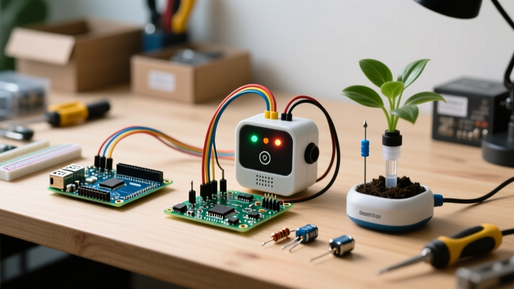
Let us calculate the theoretical battery life of an optimized, bare-bones ESP8266 soil moisture node powered by two AA Energizer Ultimate Lithium batteries (total capacity ~3000mAh at 3.0V nominal). The node wakes up every 2 hours (12 times a day), takes a reading, transmits via MQTT, and returns to deep sleep.
| Operational State | Duration | Average Current | Energy per Cycle (mAs) |
|---|---|---|---|
| Boot & Sensor Init | 150 ms | 70 mA | 10.5 |
| Fast Wi-Fi Connect (BSSID) | 450 ms | 80 mA | 36.0 |
| MQTT Publish & ACK | 200 ms | 75 mA | 15.0 |
| Deep Sleep (2 Hours) | 7200 s | 0.02 mA | 144.0 |
| Total per Cycle | ~7200.8 s | - | 205.5 mAs |
Battery Life Calculation:
Daily energy consumption = 205.5 mAs * 12 cycles = 2466 mAs (or 0.685 mAh).
Yearly consumption = 0.685 mAh * 365 = 250 mAh.
With a 3000mAh battery capacity, the theoretical lifespan is 12 years. In practice, accounting for battery self-discharge (approx. 10% per year for Lithium AA) and temperature derating, you can reliably expect 6 to 8 years of maintenance-free operation.
Common Failure Modes in Low-Power IoT Deployments
Even with perfect sleep logic, ESP8266 projects often fail in the field due to RF transmission brownouts. When the ESP8266 transmits an 802.11b/g packet, it draws transient current spikes up to 350mA for 1-2 milliseconds.
If you are powering your node from a high-ESR (Equivalent Series Resistance) source like a CR2032 coin cell, the internal resistance of the battery will cause the voltage to sag below the ESP8266's 2.5V minimum operating threshold during the TX spike. This triggers a hardware brownout reset, trapping the node in an infinite boot loop and draining the battery in days.
The Tantalum Capacitor Solution
To mitigate TX brownouts, you must place a low-ESR energy reservoir close to the ESP8266's VCC and GND pins. A standard 100µF electrolytic capacitor is often too slow to respond to microsecond RF spikes. Instead, use a 100µF to 470µF Tantalum or low-ESR MLCC (Multi-Layer Ceramic Capacitor) placed within 5mm of the ESP-12F module. This local capacitor supplies the instantaneous 350mA burst, while the main battery slowly recharges the capacitor at a sustainable 50mA continuous rate.
Summary and Next Steps
Building reliable, battery-powered ESP8266 projects requires abandoning the convenience of development boards in favor of bare modules, ultra-low quiescent LDOs, and aggressive software optimizations. By leveraging RTC memory for fast Wi-Fi connections, power-gating your sensors, and buffering RF spikes with low-ESR capacitors, you can transform the ESP8266 from a power-hungry prototyping toy into a highly efficient, multi-year IoT workhorse. For further reading on advanced RTOS sleep configurations, consult the ESP8266 RTOS SDK Sleep API documentation.