
The Type of Current Produced by Batteries is Called Direct Current (DC)
In introductory electronics, physics courses, and DIY maker spaces, a common foundational question frequently appears on quizzes and worksheets: the type of current produced by batteries is called ______. The definitive answer is Direct Current (DC). Unlike the Alternating Current (AC) that powers your home appliances and grid-tied infrastructure, the current generated by electrochemical cells flows strictly in one direction.
However, simply knowing the answer to this fill-in-the-blank question barely scratches the surface of battery-powered electronics. For electrical engineers, hobbyists, and technicians, understanding the nuanced behavior of battery-derived DC—complete with voltage sag, internal resistance, and non-linear discharge curves—is critical for designing reliable circuits. This guide explores the deep electrochemical fundamentals of battery DC, real-world failure modes, and practical power management strategies for your next DIY project.
The Electrochemical Origin of Unidirectional Flow
To understand why batteries produce Direct Current, we must look at the redox (reduction-oxidation) reactions occurring at the cellular level. A standard battery cell consists of three primary components: an anode (negative terminal), a cathode (positive terminal), and an electrolyte medium.
When a load is connected across the terminals, a chemical reaction at the anode releases electrons. Because the electrolyte acts as an ionic conductor but an electronic insulator, electrons cannot travel directly through the battery's interior. Instead, they are forced to travel through the external circuit to reach the cathode, where a corresponding reduction reaction absorbs them. This physical and chemical constraint enforces a unidirectional flow of charge, which is the very definition of Direct Current.
Core Principle: While AC generators rely on electromagnetic induction and physical rotation to periodically reverse electron flow, batteries rely on static chemical potential differences. This is why a battery will inherently only ever produce DC, never AC, without the intervention of an external oscillator or inverter circuit.
Battery Chemistries and Their DC Output Profiles
Not all Direct Current is created equal. The 'flavor' of DC produced by a battery depends heavily on its chemical composition. A lab bench power supply provides a perfectly flat, regulated DC voltage. A battery, however, provides raw, unregulated DC that slopes downward as the chemical reactants are depleted.
Below is a comparison of common battery chemistries and their specific DC output characteristics:
| Battery Chemistry | Nominal DC Voltage | Discharge Curve Profile | Internal Resistance (Typical) | Common DIY Use Case |
|---|---|---|---|---|
| Lithium-Ion (e.g., 18650) | 3.6V - 3.7V | Gradual, linear slope from 4.2V to 3.0V | 20mΩ - 40mΩ | Portable robotics, high-drain flashlights |
| Lithium Iron Phosphate (LiFePO4) | 3.2V | Extremely flat plateau around 3.2V | 10mΩ - 30mΩ | Off-grid solar banks, RV power systems |
| Lead-Acid (AGM / Flooded) | 12.0V (6-cell) | Steady decline from 12.8V to 10.5V | 5mΩ - 15mΩ (varies by CCA) | Automotive, UPS backups, heavy motor loads |
| Nickel-Metal Hydride (NiMH) | 1.2V | Flat middle section, sharp drop at depletion | 30mΩ - 100mΩ | Low-cost consumer electronics, RC toys |
Information Gain: The LiFePO4 Advantage
Notice the discharge curve profile of LiFePO4. Because its DC voltage remains incredibly stable at roughly 3.2V for 80% of its discharge cycle, it is highly favored in DIY electronics where a stable DC input is required without relying heavily on complex voltage regulation. Conversely, standard Li-ion cells require constant monitoring via a Battery Management System (BMS) to prevent the DC voltage from dropping below 2.5V, which causes irreversible copper dissolution at the anode.
Understanding DC Voltage Sag and Internal Resistance
A common beginner mistake is assuming a 12V battery will always output exactly 12V DC. In reality, the DC output is governed by Ohm's Law, factoring in the battery's internal resistance ($R_{int}$). The terminal voltage under load is calculated as:
V_terminal = V_open_circuit - (I_load × R_int)
Real-World Scenario: Let's examine a genuine Panasonic NCR18650B cell (typically priced around $7 USD). It has a nominal capacity of 3400mAh and an internal resistance of roughly 30mΩ (0.03Ω). If you connect a high-power DC motor that draws 10A upon startup, the voltage sag will be:
- Voltage Sag = 10A × 0.03Ω = 0.3V
- Terminal Voltage = 4.2V - 0.3V = 3.9V
While a 0.3V drop is manageable, counterfeit 18650 cells often have internal resistances exceeding 150mΩ. Under that same 10A load, a counterfeit cell will sag by 1.5V, dropping the DC output to 2.7V, triggering low-voltage cutoffs in your microcontroller, and generating dangerous internal heat that can lead to thermal runaway.
Managing Raw Battery DC in DIY Electronics
Because batteries produce raw, fluctuating DC, you cannot connect them directly to sensitive logic boards like an Arduino or a Raspberry Pi. You must condition the DC power. According to Texas Instruments' power management guidelines, there are two primary ways to regulate battery-derived DC:
1. Linear Regulators (LDOs)
Low Dropout Regulators (LDOs), such as the classic LM7805 or the modern AMS1117-3.3, act as variable resistors to drop excess DC voltage. They are incredibly cheap and produce 'clean' DC with virtually zero ripple. However, they dissipate excess energy as heat. If you step down a 12V lead-acid battery to 5V at 1A using an LDO, the regulator must burn off 7W of heat [(12V - 5V) × 1A], requiring a massive heatsink.
2. Switching DC-DC Converters (Buck/Boost)
Switching regulators (like the TI TPS5430 or the ubiquitous LM2596 modules found on Amazon for $2 each) use high-frequency MOSFET switching and inductors to step down (Buck) or step up (Boost) the DC voltage. They operate at 85% to 95% efficiency. If your battery voltage drops below your target logic voltage as it discharges, a SEPIC or Boost converter is mandatory to maintain a steady 5V DC output.
Troubleshooting Battery DC Circuits with a Multimeter
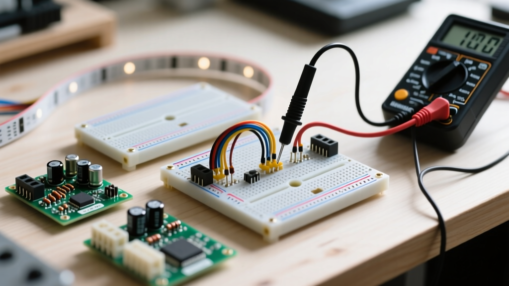
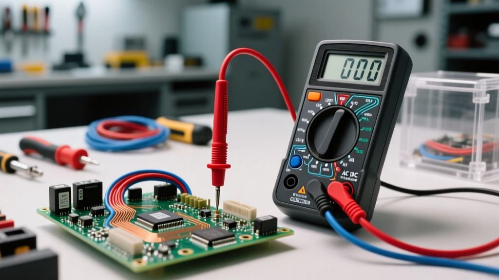
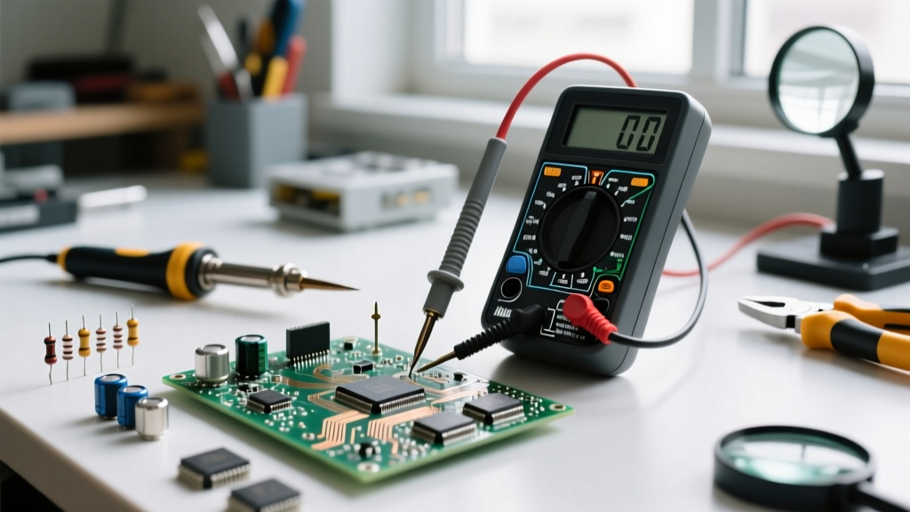
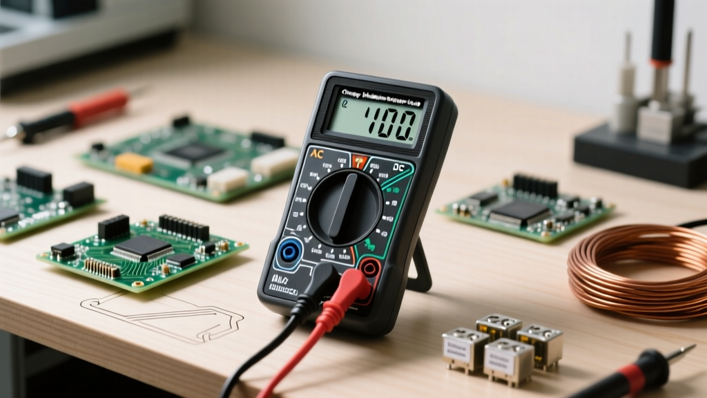
When a battery-powered DIY project fails to boot, the issue is almost always related to the quality of the DC current reaching the microcontroller. Follow this diagnostic framework using a digital multimeter (DMM):
- Measure Open-Circuit Voltage (OCV): Disconnect the battery from the circuit. Measure the DC voltage directly at the terminals. If a 12V AGM battery reads 11.4V OCV, it is roughly 20% discharged or suffering from sulfation.
- Measure Closed-Circuit Voltage (CCV): Reconnect the battery and turn the device on. Measure the voltage at the battery terminals again. A massive drop indicates high internal resistance or corroded contacts.
- Measure Voltage at the Load: Probe the DC voltage directly at the microcontroller's VIN and GND pins. If the battery reads 11.8V but the MCU reads 9.2V, you have a severe voltage drop across your wiring harness or PCB traces due to inadequate wire gauge.
Summary: Beyond the Fill-in-the-Blank
So, what is the type of current produced by batteries called? It is Direct Current (DC). But as any seasoned electrical engineer will tell you, recognizing the name is only the first step. Mastering battery DC means understanding the electrochemical limits of your chosen cell chemistry, calculating voltage sag under peak loads, and deploying the correct DC-DC switching topologies to ensure your electronics receive clean, stable power from the first charge down to the final cutoff voltage. For further reading on electrochemical fundamentals, the Battery University archives and Georgia State University's HyperPhysics portal remain indispensable resources for deep-diving into DC circuit theory.