
The Physics of the Alternating Current Coil
When designing, replacing, or troubleshooting an alternating current coil—commonly found in industrial contactors, relays, and solenoids—engineers must account for a fundamental difference from DC systems: inductive reactance. Unlike a DC coil, which limits current purely through the ohmic resistance of its copper windings, an AC coil relies on the inductive reactance ($X_L$) generated by its magnetic core to limit steady-state current.
The impedance formula dictates the behavior of the coil: $Z = \sqrt{R^2 + X_L^2}$. When the coil is first energized and the mechanical armature is open, the air gap in the magnetic circuit is large. This high reluctance keeps the inductance ($L$) extremely low, resulting in a low $X_L$ and a massive inrush current. Once the armature pulls in and seals against the core, the air gap vanishes, inductance spikes, $X_L$ increases dramatically, and the current drops to a fraction of an ampere, known as the sealed or holding current.
Expert Insight: If an alternating current coil is energized but the mechanical armature is physically blocked from sealing, the inrush current will continue to flow. Because AC magnet wire is sized for the lower sealed current, this sustained high current will rapidly overheat the coil, melt the enamel insulation, and cause a short-circuit failure within minutes.
Control Circuit Wire Sizing Chart for AC Coils
Wire sizing for an AC coil application involves two distinct domains: the micro-gauge magnet wire used to wind the coil, and the macro-gauge control wire used to supply the coil. The chart below focuses on the control circuit supply wire. According to NEMA ICS 2 standards, an alternating current coil must reliably pull in at 85% of its rated voltage and withstand 110% without thermal degradation. Therefore, control wire must be sized to prevent voltage drop below the 85% threshold during the high-inrush startup phase.
| Rated AC Voltage | Typical Inrush VA | Typical Sealed VA | Inrush Current (A) | Min Wire Gauge (50 ft run) | Voltage Drop @ Inrush |
|---|---|---|---|---|---|
| 24V AC | 150 VA | 10 VA | 6.25 A | 10 AWG | 1.5% |
| 120V AC | 300 VA | 15 VA | 2.50 A | 14 AWG | 1.2% |
| 208V AC | 450 VA | 25 VA | 2.16 A | 14 AWG | 0.7% |
| 240V AC | 500 VA | 30 VA | 2.08 A | 14 AWG | 0.6% |
| 480V AC | 800 VA | 40 VA | 1.66 A | 16 AWG | 0.3% |
Note: Wire gauges listed assume copper conductors at 75°C and a single-phase control circuit. For runs exceeding 100 feet, always calculate exact voltage drop using the specific inrush current of your contactor model.
Magnet Wire Selection for Rewinding AC Coils
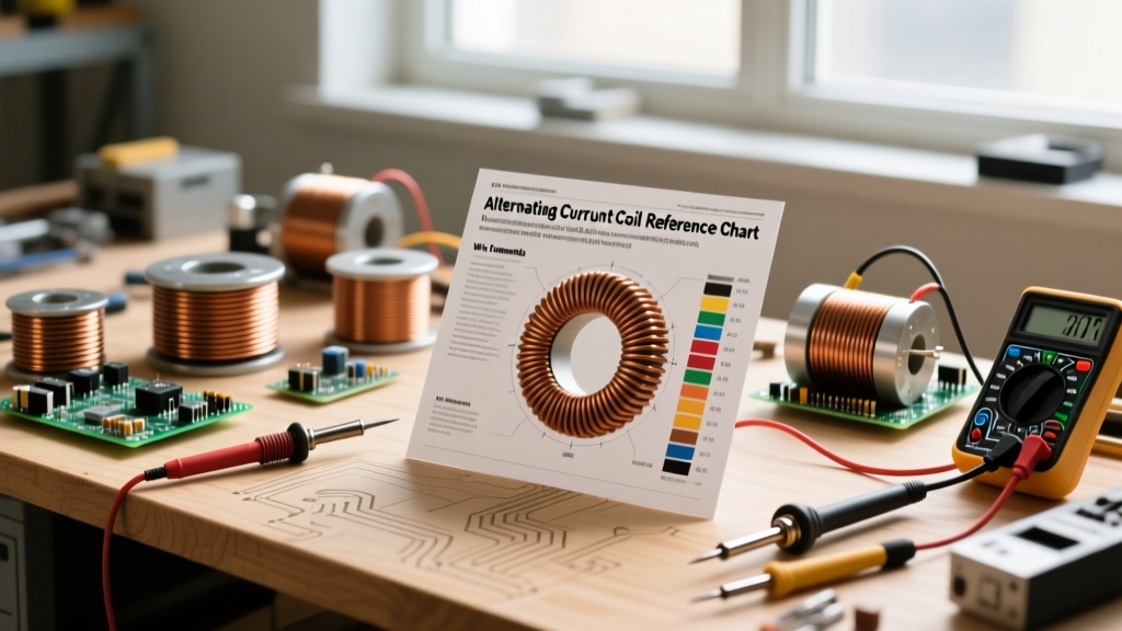
When rewinding a damaged alternating current coil, selecting the correct magnet wire (enameled copper wire) is critical. The wire gauge typically ranges from 28 AWG to 42 AWG, depending on the coil's voltage rating and physical bobbin size.
Thermal Class Ratings
Industrial AC coils operate in high-ambient-temperature environments, such as inside enclosed motor control centers (MCCs). You must match the thermal class of the magnet wire enamel to the application:
- Class B (130°C): Standard for light-duty relays and HVAC contactors.
- Class F (155°C): The industry standard for heavy-duty NEMA and IEC industrial contactors.
- Class H (180°C): Required for high-ambient environments, such as steel mills or marine engine rooms.
When calculating the number of turns, maintain the original fill factor. If you use a thicker wire (lower AWG) to compensate for a burnout, you will not fit the required number of turns. This reduces the total inductance, increasing the sealed current and guaranteeing a premature thermal failure.
The Shading Ring: Preventing AC Chatter
A unique feature of the alternating current coil is the requirement for a shading ring (or shading coil). Because 60Hz AC power crosses the zero-voltage point 120 times per second, the magnetic flux collapses to zero twice every cycle. Without intervention, the armature would rapidly open and close at 120Hz, resulting in a loud, destructive hum known as 'chatter'.
To prevent this, a heavy copper or aluminum ring is embedded in the face of the stationary iron core. This ring acts as a short-circuited secondary winding. As the main AC flux collapses, the changing magnetic field induces a current in the shading ring. This induced current generates its own secondary magnetic flux, which is slightly out of phase with the main flux. This secondary flux holds the armature sealed during the zero-crossings, ensuring smooth, silent operation. If this shading ring cracks or breaks off, the contactor will buzz violently and eventually destroy its own mechanical housing.
Common Failure Modes and Diagnostics
According to troubleshooting guidelines published by Fluke, AC coil failures are rarely random; they are almost always symptomatic of underlying circuit or mechanical issues. Use this diagnostic framework to identify the root cause:
1. Undervoltage Burnout
Symptom: The coil is blackened, and the enamel is melted, but the control circuit breaker did not trip.
Root Cause: The supply voltage dropped below 85% of the rated value. As noted in Schneider Electric's voltage tolerance documentation, undervoltage prevents the armature from fully sealing. The sustained air gap keeps the impedance low, drawing continuous inrush current until the insulation fails.
2. Overvoltage Insulation Breakdown
Symptom: A dead short between the magnet wire windings and the grounded steel core.
Root Cause: Sustained operation above 110% of the rated voltage. This forces excessive magnetic saturation and generates heat beyond the enamel's dielectric strength, leading to turn-to-turn shorts.
3. Moisture and Contamination Tracking
Symptom: Ground fault trips when the coil is energized.
Root Cause: Conductive dust or moisture creates a tracking path from the live coil terminals to the grounded core. This is common in washdown environments where IP67-rated enclosures have failed.
Best Practices for Installation
To maximize the lifespan of an alternating current coil, always verify the control voltage at the coil terminals while the coil is actively pulling in. Measuring voltage at the PLC output or control transformer is insufficient; you must measure at the load side under inrush conditions to ensure the voltage drop across the control wiring does not starve the coil. Furthermore, ensure the mechanical armature moves freely; even a slight buildup of rust or debris on the core mating surfaces can act as an artificial air gap, reducing inductance and elevating the sealed holding current to dangerous thermal levels.
For deeper theoretical analysis on inductive reactance and AC magnetic circuits, refer to the comprehensive chapters on inductive AC circuits at All About Circuits. Understanding the interplay between mechanical positioning and electrical impedance is the hallmark of a true electrical diagnostics expert.