
When you plug a lamp into a wall outlet, you are tapping into a highly engineered, continuously oscillating energy system. While many DIYers and junior electricians understand the basic math of Ohm's Law, the actual physics of alternating current (AC) and how it behaves inside copper conductors is often misunderstood. Understanding how does AC electricity work in real-world applications is critical for proper wire sizing, safe circuit troubleshooting, and designing reliable microcontroller power supplies.
The Core Mechanism: Alternating Current in Motion
Unlike Direct Current (DC), where electrons flow continuously in a single direction from the negative to the positive terminal, AC electricity involves electrons that rapidly oscillate back and forth. In North America, the standard grid frequency is 60 Hertz (Hz). This means the current changes direction 120 times per second (completing 60 full sine wave cycles).
This oscillation is generated at the power plant via electromagnetic induction. As a turbine spins a massive magnet inside a coil of wire, the changing magnetic field forces electrons to surge forward, slow down, stop, and reverse direction. According to All About Circuits, this sine wave delivery is vastly superior for long-distance transmission because AC voltage can be easily stepped up to hundreds of thousands of volts using transformers, drastically reducing I²R (heat) losses over transmission lines, and then stepped down for residential use.
RMS vs. Peak Voltage: What Your Multimeter Actually Reads
One of the most dangerous misconceptions in residential wiring is assuming a 120V outlet only ever experiences 120 volts. Because AC voltage is a constantly changing sine wave, it spends a significant amount of time near zero. If we simply averaged the voltage, it would be useless for power calculations.
To solve this, engineers use Root Mean Square (RMS) voltage. RMS is the equivalent DC voltage that would produce the exact same heating effect in a resistive load. When your multimeter reads 120V, it is reading the RMS value. However, the peak voltage of that sine wave is actually about 1.414 times the RMS value.
| Parameter | Value (US Standard) | Real-World Application & Implication |
|---|---|---|
| RMS Voltage | 120V | What your multimeter reads; used for calculating wattage (W = V × A). |
| Peak Voltage | ~170V | The maximum instantaneous voltage. Dictates insulation stress and capacitor ratings. |
| Peak-to-Peak | ~340V | The total voltage swing from the positive peak to the negative peak. |
Pro-Tip for DIYers: Never size a capacitor for an AC motor repair or a DIY power supply based solely on the RMS voltage. Always ensure the capacitor's DC voltage rating exceeds the AC peak voltage (170V for a 120V circuit, or 340V for a 240V circuit) to prevent catastrophic dielectric failure and explosion.
Split-Phase Power: The 240V/120V Residential Standard
To understand how AC electricity works in a home, you must understand the split-phase transformer. The U.S. Energy Information Administration (EIA) notes that residential power is delivered via a center-tapped step-down transformer mounted on a utility pole or pad.
This transformer steps the grid's high voltage down to 240V across the entire secondary winding. A neutral wire is connected to the exact center of this winding (the center tap), splitting the 240V into two 120V legs (L1 and L2). Because L1 and L2 are drawn from opposite ends of the coil, their sine waves are 180 degrees out of phase. When L1 is at its positive peak of +170V, L2 is at its negative peak of -170V. The potential difference between them is 340V peak (240V RMS), which is used for heavy appliances like electric ranges, dryers, and EV chargers. Standard 120V receptacles simply use one hot leg and the center-tapped neutral.
The Skin Effect: Does AC Change Wire Sizing Rules?
A frequent question in wire sizing is whether AC behaves differently than DC inside a conductor. The answer lies in the skin effect. When AC flows through a wire, the changing magnetic field induces eddy currents that push the electron flow toward the outer surface (the "skin") of the conductor. This effectively reduces the usable cross-sectional area of the wire, increasing its AC resistance compared to its DC resistance.
However, context is everything. At the standard 60Hz grid frequency, the skin depth in copper is approximately 8.5 millimeters. Because standard residential wiring (like 14 AWG, 12 AWG, or even 4 AWG) has a diameter much smaller than 17mm, the current distributes evenly across the entire wire. For standard home wiring, the skin effect is negligible, and AC ampacity tables match DC capabilities.
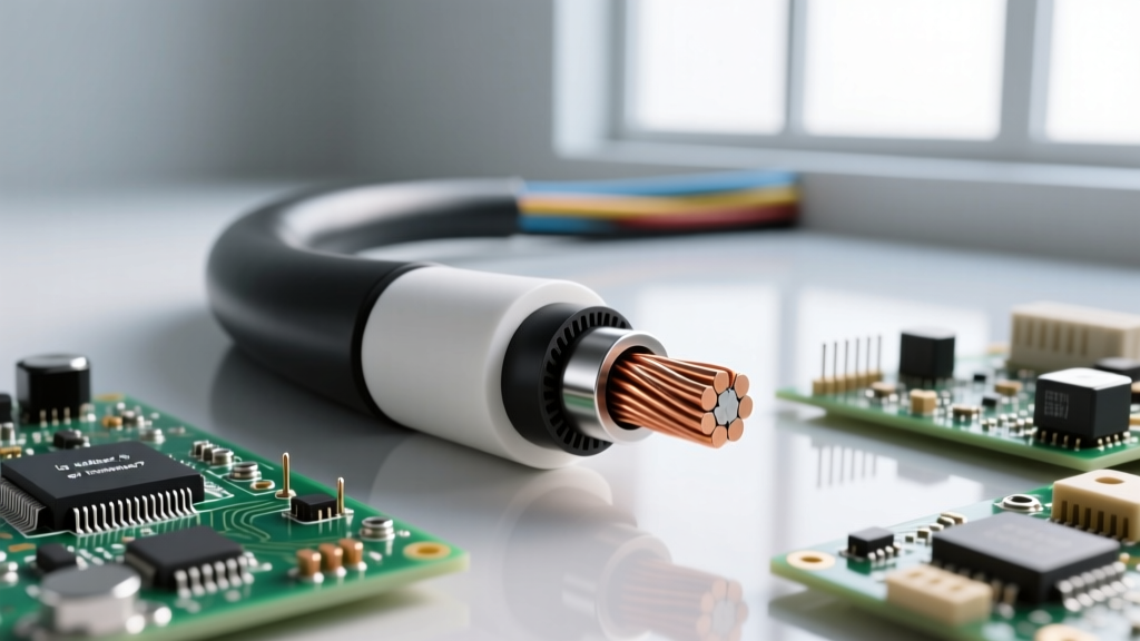
The real-world application changes drastically in industrial settings. If you are wiring a Variable Frequency Drive (VFD) that outputs high-frequency PWM (Pulse Width Modulation) signals to a motor, the skin effect becomes severe. In these scenarios, electricians must use specialized VFD-rated cables with finely stranded conductors to maximize surface area, or derate standard wire sizing tables to prevent overheating.
Troubleshooting Real-World AC Anomalies
Because AC relies on oscillating magnetic fields and complex phase relationships, it introduces unique failure modes that DC systems do not experience. Recognizing these is crucial for any electrical troubleshooter.
Ghost Voltages and Inductive Coupling
Have you ever used a high-impedance digital multimeter to test a dead circuit, only to read 40V or 60V on a disconnected wire? This is a "ghost voltage." In real-world AC wiring, cables are often bundled tightly together in walls and conduits. The alternating magnetic field from a live "hot" wire induces a tiny capacitive voltage in the adjacent dead wire. According to testing by Fluke, these ghost voltages lack the current (amperage) to do any work or shock you, but they can confuse beginners into thinking a circuit is still live. Using a low-impedance voltage tester or a solenoid-style "wiggy" tester will safely drain this capacitive coupling and read a true zero.
Floating Neutrals in Split-Phase Systems
One of the most destructive real-world AC failures is a broken or "floating" neutral on the main service drop. Because the neutral wire is the physical center-tap of the transformer, it acts as the anchor for the 120V circuits. If the neutral connection corrodes or snaps at the weatherhead, L1 and L2 become a single 240V series circuit.
In this scenario, your home's 120V appliances act as resistors in a voltage divider. If the living room TV (low resistance) is on L1, and the kitchen toaster (high resistance) is on L2, the 240V will divide unevenly. The TV might receive 200V (instantly frying its power supply), while the toaster receives only 40V. If you ever notice lights in your home getting unusually bright when a heavy appliance turns on, immediately shut off the main breaker and call an electrician—this is the hallmark symptom of a floating neutral in an AC split-phase system.
Understanding the physics of AC electricity—from RMS peaks and split-phase vectors to high-frequency skin effects—bridges the gap between theoretical electronics and safe, code-compliant real-world wiring.