
The Core Question: How Do Batteries Make Electricity?
When you are building a DIY solar generator, wiring an off-grid RV, or designing a custom microcontroller power bank, you are ultimately relying on stored chemical energy. But how do batteries make electricity in a way that we can harness for our circuits? At the most fundamental level, a battery is an electrochemical cell that converts chemical potential energy directly into direct current (DC) electrical energy.
Inside a standard cell, there are three primary components: the anode (negative terminal), the cathode (positive terminal), and the electrolyte. According to the U.S. Department of Energy, the electrolyte acts as a selective barrier. It allows ions (charged atoms) to pass through but strictly blocks electrons. When you connect a conductive wire between the anode and cathode, you provide a path of least resistance for the electrons. The chemical reaction at the anode forces electrons into the wire, creating an electrical current that powers your load before returning to the cathode. This continuous flow of electrons is what we measure as DC electricity.
Real-World Translation: From Chemical Energy to Usable DC Power
Understanding the electrochemical theory is useful, but as DIYers and electrical hobbyists, we need to know how this translates to real-world voltage, current, and load management. When you connect a 12V inverter to a battery bank, the chemical reaction must physically sustain the electron flow demanded by the load.
The Role of Internal Resistance and Voltage Sag
No battery is a perfect voltage source. Every cell possesses internal resistance (IR), which is the opposition to the flow of current within the battery's own electrolyte and electrodes. As detailed by Battery University, internal resistance is the primary culprit behind voltage sag.
Let us look at a real-world scenario. Suppose you are running a 12V DC compressor fridge that pulls 10 Amps upon startup. If you are using a brand-new Lithium Iron Phosphate (LiFePO4) battery with an internal resistance of 2 milliohms (0.002 ohms), the voltage drop is calculated using Ohm’s Law (V = I × R):
- LiFePO4 Voltage Sag: 10A × 0.002Ω = 0.02V drop. The battery maintains a rock-solid 13.2V under load.
- Aged AGM Lead-Acid Voltage Sag: An older Absorbent Glass Mat battery might have an IR of 15 milliohms (0.015Ω). 10A × 0.015Ω = 0.15V drop. While small, if the fridge requires a 50A surge to start the compressor, the drop becomes 0.75V, which can trigger low-voltage disconnects in sensitive electronics.
This is why understanding how batteries make electricity is only half the battle; managing their internal limitations under dynamic loads is where real-world engineering happens.
Battery Chemistries in Action: A Practical Comparison
Different chemical reactions yield vastly different electrical characteristics. When sizing a system, you must match the chemistry to the application. Below is a practical comparison of the three most common chemistries used in DIY electrical projects.
| Chemistry | Nominal Voltage | Usable Capacity (DoD) | Internal Resistance | Best DIY Application |
|---|---|---|---|---|
| Lead-Acid (Flooded) | 12.0V (6 cells) | 50% | High (increases with age) | Low-budget off-grid, backup sump pumps |
| AGM / Gel | 12.0V | 50% - 80% | Medium | RV house banks, marine starting batteries |
| LiFePO4 (Lithium) | 12.8V (4 cells) | 90% - 100% | Extremely Low | Solar generators, high-draw inverters, daily cycling |
Notice the usable capacity, or Depth of Discharge (DoD). A 100Ah Lead-Acid battery only provides 50Ah of real-world electricity before sulfation damages the plates. A 100Ah LiFePO4 battery provides nearly 100Ah, fundamentally changing how you calculate your wire sizing and system autonomy.
Sizing Wires for Battery Banks: Avoiding the Bottleneck
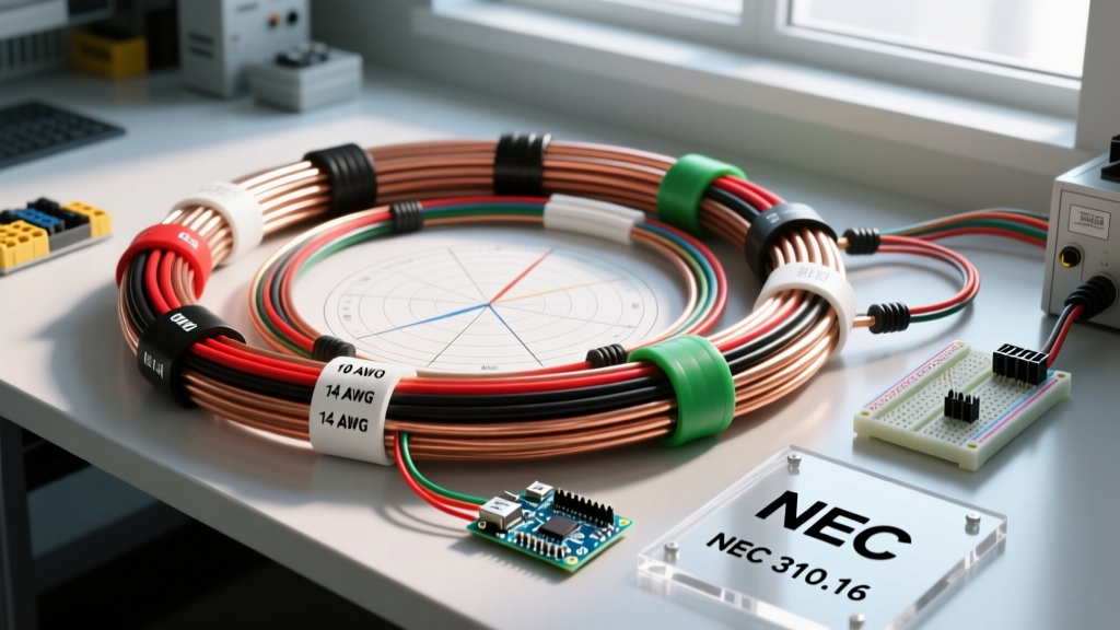
Because batteries produce DC electricity, the current (Amps) required to deliver high wattage is significantly higher than in standard AC household wiring. This is a critical concept in wire sizing fundamentals. Power (Watts) = Voltage × Current.
If you connect a 2000W inverter to a 12V battery bank, the continuous current draw is roughly 166 Amps (2000W / 12V), and surge draws can exceed 300 Amps. If you attempt to wire this using standard 10 AWG copper wire (rated for roughly 30A in chassis wiring), the wire will act as a resistor, generating immense heat and potentially causing an electrical fire.
Real-World Failure Mode: The Melted Terminal Syndrome
A common mistake in DIY battery builds is focusing on the wire gauge while ignoring the terminal connections. How do batteries make electricity efficiently if the connection point is flawed? They do not. If a battery terminal is not torqued correctly or suffers from oxidation, it introduces contact resistance.
Expert Troubleshooting Insight: If a loose terminal introduces just 10 milliohms (0.01Ω) of contact resistance, and your inverter pulls 150 Amps, the heat dissipated at that single connection point is calculated by P = I²R. That equals 150² × 0.01 = 225 Watts of pure heat concentrated on a tiny lead post. This will melt the battery terminal, destroy the cable lug, and create a severe fire hazard. Always use a calibrated torque wrench and apply anti-oxidant compound to battery terminals.
For a 12V, 2000W inverter setup, you should use a minimum of 2/0 AWG (double-aught) pure copper welding cable for runs up to 5 feet to maintain a voltage drop of less than 3%. Always size your wires based on the maximum surge current, not just the continuous rating.
Best Practices for Maximizing Battery Lifespan in Off-Grid Setups
Understanding the electrochemical generation of electricity also reveals why batteries degrade. Every time electrons are forced through the circuit, the physical structure of the anode and cathode undergoes micro-stresses.
- Temperature Management: Chemical reactions are temperature-dependent. While a cold battery suffers from increased internal resistance (reducing available current), charging a lithium battery below freezing (32°F / 0°C) causes lithium plating on the anode, permanently destroying the cell. Always use batteries with built-in low-temperature charge protection in unheated DIY enclosures.
- Peukert’s Law: For lead-acid chemistries, the faster you draw electricity, the less total capacity is available. A 100Ah battery rated at a 20-hour discharge rate (5A draw) might only yield 60Ah of capacity if discharged at a 1-hour rate (60A draw). LiFePO4 batteries are largely immune to the Peukert effect, making them vastly superior for high-draw DIY projects like induction cooktops or microwaves.
- The SEI Layer: In lithium-ion and LiFePO4 cells, the Solid Electrolyte Interphase (SEI) layer forms on the anode during the first few charge cycles. This layer protects the electrolyte from continuous degradation. Deep discharges and extreme heat cause the SEI layer to crack and reform, consuming active lithium and increasing internal resistance over time. Keeping your battery bank between 20% and 80% state-of-charge during daily use will exponentially increase its cycle life.
Final Thoughts on Electrochemical Power
Ultimately, answering the question of how do batteries make electricity requires looking past the basic science and into the practical realities of resistance, chemistry, and thermal dynamics. By respecting the internal limitations of your cells, properly sizing your DC conductors, and managing your terminal connections, you can build robust, safe, and highly efficient off-grid power systems that will serve your DIY projects for years to come.