
The Anatomy of a Failure: Why Your Stepper Stalls and Jitters
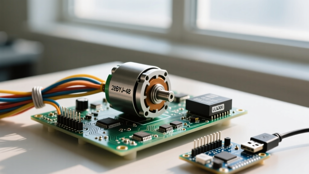
The ubiquitous 28BYJ-48 (often searched as the 28bjy 48 stepper motor) is the cornerstone of DIY robotics, automated blinds, and camera sliders. Priced at roughly $3 to $5 per unit, it is an inexpensive unipolar stepper motor paired with a ULN2003 Darlington transistor driver board. However, its low cost comes with distinct mechanical and electrical quirks. When your motor stalls, vibrates loudly, or loses positional accuracy, the issue rarely stems from the microcontroller itself. Instead, failures typically cascade from three areas: power supply brownouts, cumulative gear-ratio errors, or improper coil sequencing.
In this comprehensive troubleshooting guide, we will bypass generic advice and dive into the exact multimeter readings, timing parameters, and hardware modifications required to stabilize your 28BYJ-48 setup.
The Gear Reduction Anomaly: 64:1 vs. 63.68:1
Before diagnosing electrical faults, you must understand the mechanical reality of the 28BYJ-48. The manufacturer's datasheet claims a gear reduction ratio of exactly 64:1. Based on a motor stride angle of 5.625°, this implies 4096 steps per full revolution (360° / 5.625° * 64). However, teardowns and empirical testing reveal the actual gear train ratio is 63.68395:1.
This discrepancy results in exactly 4075.77 steps per revolution. If your Arduino code is programmed to move exactly 4096 steps to complete a 360° rotation, your motor will overshoot by roughly 1.8° every single revolution. Over 20 rotations, this cumulative error results in a massive 36° positional drift. The Fix: Update your steps-per-revolution constant in your firmware to 4075.77 (or 4076 for integer math) rather than the default 4096.
ULN2003 Driver Board: Diagnosing the Blinking LEDs
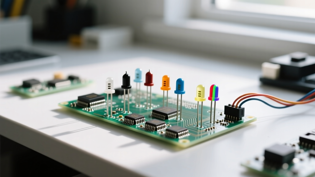
The ULN2003 driver board acts as the bridge between your microcontroller's low-current logic pins and the motor's high-current coils. It features four indicator LEDs (IN1 to IN4) that should sequence in a specific pattern. If your motor is vibrating but not turning, observe the LEDs.
| LED Sequence State | Motor Behavior | Diagnostic Conclusion |
|---|---|---|
| All 4 LEDs Blinking Rapidly | High-pitched buzzing, no rotation | Step delay is too low (under 2ms). The motor cannot overcome rotor inertia. |
| 1 or 2 LEDs Stuck ON | Motor holds position, gets extremely hot | Microcontroller pin is locked HIGH. Check for infinite loops or crashed I2C buses. |
| LEDs Sequencing Correctly | Motor stutters or misses steps | Power starvation. The ULN2003 is starved of current due to voltage drop. |
Thermal Throttling and the Darlington Voltage Drop
The ULN2003 utilizes Darlington pairs to sink current. According to the Texas Instruments ULN2003A Datasheet, a Darlington configuration inherently suffers from a higher collector-emitter saturation voltage (VCE(sat))—typically around 1.0V to 1.4V at 200mA. If you are powering the board at 5V, the motor coils only see about 3.6V. This reduces your torque by nearly 28%. If the ULN2003 chip feels too hot to touch, it is dissipating excess wattage. Ensure the board's jumper cap (bridging VCC and the motor power rail) is firmly seated, and consider upgrading to a 12V variant of the 28BYJ-48 if continuous high-torque operation is required.
Wiring & Power Starvation: The 5V Brownout Dilemma
The most frequent cause of erratic 28bjy 48 stepper motor behavior is routing motor power through the Arduino's onboard 5V linear regulator. The motor draws approximately 240mA when all phases are energized. An Arduino Uno's USB port is typically limited to 500mA, and the onboard AMS1117-5.0 voltage regulator can safely dissipate only about 800mA before thermal shutdown.
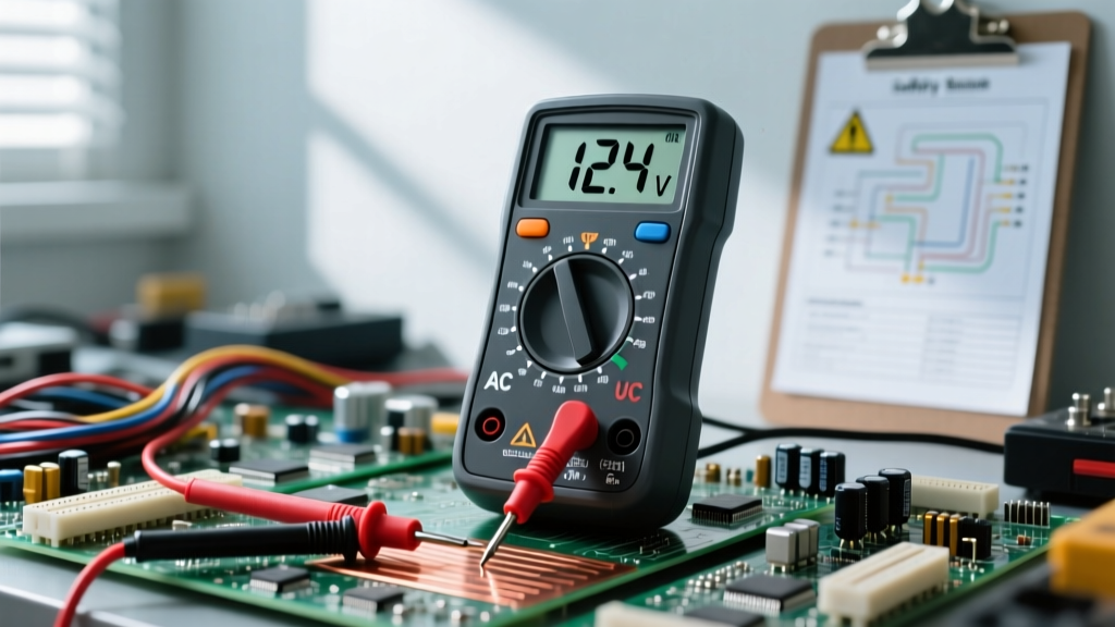
Measuring Coil Resistance with a Multimeter
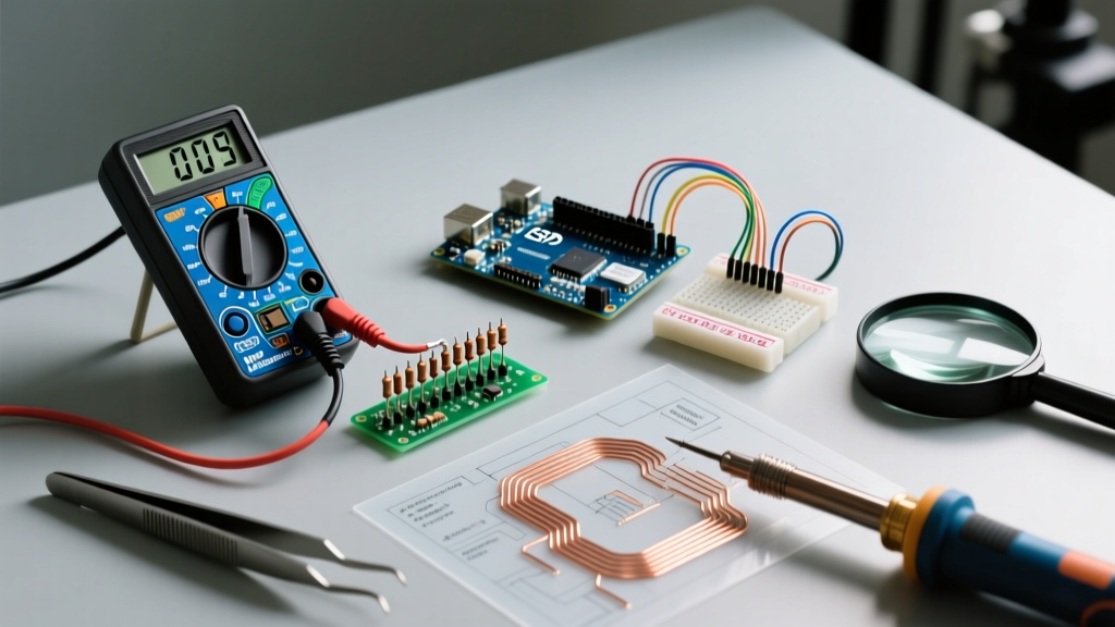
To verify your motor's internal health, disconnect it from the ULN2003 and set your multimeter to the 200Ω resistance range. The 5-pin JST connector follows a specific color code:
- Red (Pin 3): Common Center-Tap (VCC)
- Pink & Orange (Pins 1 & 2): Coil 1 (A and B)
- Yellow & Blue (Pins 4 & 5): Coil 2 (C and D)
Place one probe on the Red wire and the other on the Pink wire. You should read approximately 50Ω. Repeat for Red-to-Orange, Red-to-Yellow, and Red-to-Blue. If you measure an open loop (OL) or infinite resistance on any phase, the internal copper winding is severed, and the motor must be replaced. Conversely, if you measure near 0Ω, an internal short has occurred.
Arduino Code & Timing: Fixing Microsecond Jitter
Using the default Arduino Stepper.h library often leads to blocking code. When the microcontroller executes stepper.step(), it halts all other operations, including sensor polling and serial communication. This blocking behavior causes timing jitter, leading to missed micro-steps and audible grinding.
Migrating to the AccelStepper Library
To achieve smooth acceleration and non-blocking operation, you must use the AccelStepper Library. This library calculates trapezoidal speed profiles, preventing the motor from being commanded to exceed its physical pull-in torque limit.
#include <AccelStepper.h>

// Define the motor interface type and pin sequence
// FULL4WIRE is critical for the 28BYJ-48 half-step/full-step sequencing
AccelStepper stepper(AccelStepper::FULL4WIRE, 8, 10, 9, 11);

void setup() {
  // The 28BYJ-48 max reliable speed is ~500 RPM (approx 1000 steps/sec)
  stepper.setMaxSpeed(1000.0);
  // Set acceleration to prevent rotor stall on startup
  stepper.setAcceleration(500.0);
  // Target position in steps (using the corrected 4076 ratio)
  stepper.moveTo(4076);
}

void loop() {
  // Non-blocking step execution
  stepper.run();
}
Notice the pin mapping: 8, 10, 9, 11. The physical wiring on the ULN2003 board usually dictates IN1=8, IN2=9, IN3=10, IN4=11. However, the AccelStepper library requires the pins to be passed in the order of the coil phases (A, B, C, D), which corresponds to IN1, IN3, IN2, IN4. Misordering these pins will result in the motor vibrating violently in place.
Mechanical Backlash and Physical Limitations
Even with perfect wiring and optimized code, the 28BYJ-48 suffers from inherent mechanical backlash. The internal gear train is constructed from sintered metal and plastic spur gears. When reversing direction, you will experience up to 0.5° of dead-zone travel before the output shaft engages.
For applications requiring bidirectional precision (such as a CNC plotter or a laser pointer), this backlash is unacceptable. The Fix: Implement software backlash compensation by always approaching your target coordinate from the same direction, or upgrade to a NEMA 17 stepper motor paired with an A4988 or TMC2209 driver for zero-backlash, high-torque applications. For further reading on upgrading your motion systems, consult this comprehensive 28BYJ-48 Stepper Motor Arduino Tutorial which details the exact thresholds where hobbyists should transition to industrial-grade NEMA steppers.
Summary Checklist for Rapid Diagnostics
- Motor Vibrates but Won't Turn: Check AccelStepper pin mapping order (IN1, IN3, IN2, IN4) and increase step delay.
- Positional Drift: Change steps-per-revolution from 4096 to 4076.
- Arduino Resets Randomly: Isolate motor power using a dedicated 5V 2A buck converter; do not share the Arduino 5V rail.
- Motor Gets Excessively Hot: Ensure your code de-energizes the coils when stationary using
stepper.disableOutputs().