
The Undisputed Workhorse of Modern Electronics
Every electrical engineer, PCB designer, and DIY hobbyist eventually stares at a tiny, tan, rectangular component on a schematic and wonders about its exact physical specifications. The 100nF (0.1µF) capacitor is the undisputed workhorse of modern electronics. Whether you are decoupling the VCC pin of an ATmega328P, filtering noise on an analog sensor line, or stabilizing the power rail of a high-speed ARM Cortex-M7 microcontroller, the 100nF capacitor is your first line of defense against transient voltage spikes and electromagnetic interference (EMI).
However, simply typing '100nF capacitor' into a distributor's search bar is a recipe for suboptimal circuit performance. The physical package, dielectric material, and voltage rating drastically alter how the component behaves in the real world. This comprehensive buying guide will decode the standard 100nF capacitor code, dissect the hidden traps of DC bias derating, and provide a professional framework for selecting the exact right component for your next Bill of Materials (BOM).
Cracking the 100nF Capacitor Code: Markings Explained
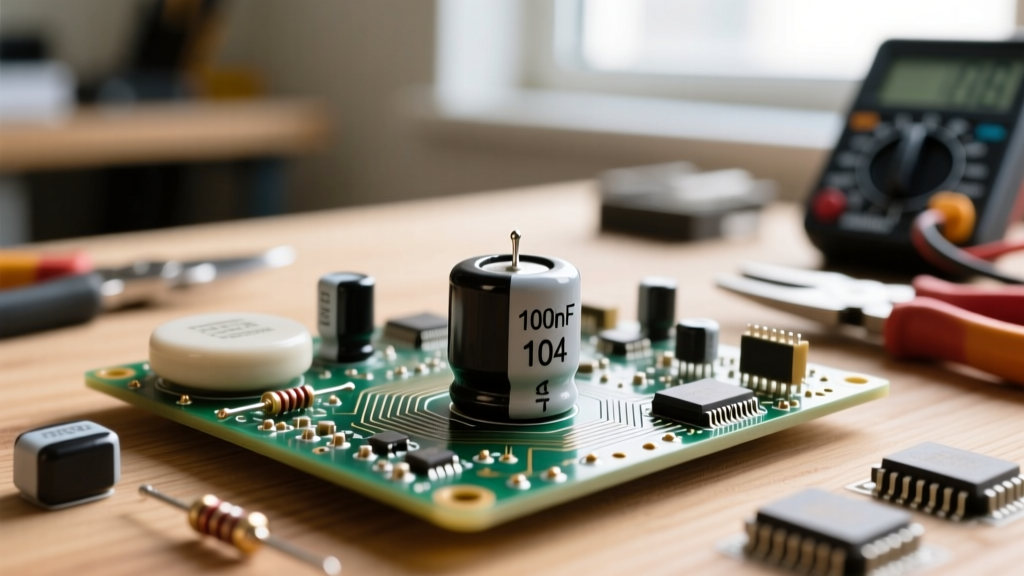
Unlike resistors, which often use color bands, modern ceramic capacitors rely on the EIA (Electronic Industries Alliance) 3-digit marking system. If you are looking at a through-hole ceramic disc capacitor or a larger surface-mount device (SMD), you will almost universally see the code 104 printed on the casing.
The '104' Standard Decoded
The 3-digit code is a shorthand for the capacitance value measured in picofarads (pF). The first two digits represent the significant figures, and the third digit is the multiplier (the number of zeros to add).
- First two digits: 10
- Multiplier: 4 (meaning add four zeros)
- Calculation: 10 × 10,000 = 100,000 pF
- Conversion: 100,000 pF = 100 nF = 0.1 µF
Therefore, whenever you see 104 on a component, you are looking at a 100nF capacitor. For a deeper dive into basic component identification and capacitor theory, the SparkFun Capacitor Tutorial offers an excellent foundational overview of how these components store and release charge.
Tolerance and Voltage Sub-Codes
The '104' code is often followed by a letter indicating the manufacturing tolerance. When buying for precision timing circuits or analog filters, this letter is critical:
- J: ±5% (High precision, usually C0G/NP0 dielectric)
- K: ±10% (Standard for X7R decoupling)
- M: ±20% (Acceptable for bulk bypass)
- Z: +80% / -20% (Avoid for critical designs)
On surface-mount ceramics, you may also see a letter denoting the voltage rating based on EIA-96 standards. For example, in Murata's part numbering scheme, a '1H' denotes 50V, while '1C' denotes 16V.
Dielectric Selection: Why X7R Dominates the BOM
The most critical buying decision you will make is not the capacitance value, but the dielectric material. The dielectric dictates the capacitor's temperature stability, voltage coefficient, and physical size. According to the Murata Dielectric Knowledge Base, ceramic capacitors are divided into Class 1 (stable) and Class 2 (high volumetric efficiency) materials.
| EIA Code | Class | Temp Range | Capacitance Shift | Best Application |
|---|---|---|---|---|
| C0G / NP0 | Class 1 | -55°C to +125°C | ±30 ppm/°C (Near Zero) | RF filters, precision timing, audio crossovers |
| X7R | Class 2 | -55°C to +125°C | ±15% over temp | General decoupling, I2C/SPI pull-ups, bypass |
| X5R | Class 2 | -55°C to +85°C | ±15% over temp | Consumer electronics, low-cost MCU boards |
| Y5V | Class 2 | -30°C to +85°C | +22% / -82% (Extreme) | None (Avoid in professional designs) |
Buyer's Verdict: For 95% of digital decoupling applications (placing a cap across the VCC and GND pins of an IC), X7R is the gold standard. It offers a great balance of physical size and temperature stability. However, if your 100nF capacitor is being used in an active RC filter, an oscillator, or an audio signal path, you must pay the premium for C0G/NP0. Class 2 dielectrics like X7R exhibit piezoelectric microphonics, meaning they can actually generate voltage when subjected to mechanical vibration, introducing severe noise into analog audio circuits.
The Hidden Trap: DC Bias and Capacitance Droop
Here is where amateur buyers and even some junior engineers make a catastrophic BOM error. The '100nF' value printed on the reel is measured at 0V DC bias and a low AC test signal (usually 1Vrms at 1kHz).
Class 2 dielectrics (X7R, X5R) suffer from a phenomenon known as DC Bias Effect. As you apply a DC voltage across the capacitor, the internal dipoles in the barium titanate dielectric align and 'lock' into place, severely reducing the material's permittivity.
The 50% Derating Rule: A 100nF X7R capacitor in a tiny 0402 package rated for 16V might only provide 20nF to 30nF of actual capacitance when 12V of DC bias is applied. If you are decoupling a 12V motor driver, your '100nF' cap is effectively a 25nF cap in operation.
How to buy around this trap: Always select a voltage rating that is at least double your maximum rail voltage. If your rail is 5V, buy a 10V or 16V rated capacitor. Furthermore, larger physical package sizes (like 0805) suffer significantly less from DC bias droop than smaller packages (like 0402) because the dielectric layers are thicker and subjected to lower electrical field stress. For a rigorous technical breakdown of this phenomenon, refer to the Vishay Ceramic Capacitors Application Guide.
Package Sizes and Parasitic Inductance (ESL)
When buying SMD 100nF capacitors for high-speed digital boards (e.g., FPGAs, DDR memory, or 100MHz+ microcontrollers), the physical footprint dictates the Equivalent Series Inductance (ESL).
- 0805 (2.0mm x 1.25mm): Easy to hand-solder. Higher ESL. Self-Resonant Frequency (SRF) is lower. Good for power supply bulk filtering.
- 0603 (1.6mm x 0.8mm): The industry standard for general-purpose prototyping and hand-assembly. Good balance of ESL and solderability.
- 0402 (1.0mm x 0.5mm): Lowest ESL and highest SRF. Mandatory for placing directly under the pins of high-speed BGA chips to suppress GHz ringing. Requires a microscope and reflow oven for reliable assembly.
Remember: A capacitor acts as an inductor above its Self-Resonant Frequency. To effectively decouple a 200MHz clock harmonic, you need a 0402 package to keep the ESL below 0.5nH, ensuring the capacitor's impedance remains low at those high frequencies.
Real-World Purchasing Checklist & Trusted Brands
When adding 100nF capacitors to your Mouser, Digi-Key, or Farnell cart, use this checklist to ensure you are getting reliable parts:
- Verify the Dielectric: Search specifically for 'X7R' or 'C0G'. Avoid unmarked listings.
- Check the DC Bias Graph: Use the distributor's datasheet link to verify the capacitance retention at your operating voltage.
- Stick to Tier-1 Manufacturers: Buy from Murata (GRM series), TDK (C series), KEMET (C series), or Vishay.
- Avoid Counterfeits: Never buy ceramic decoupling capacitors from unauthorized marketplaces like AliExpress or eBay for production runs. Counterfeit caps often contain internal voids that lead to catastrophic short-circuit failures when exposed to reflow temperatures.
Recommended Part Numbers for Your Next Design
- Murata GRM155R71H104KA88D: 0402, 100nF, X7R, 50V. The ultimate high-speed decoupling standard.
- KEMET C0805C104K5RACTU: 0805, 100nF, X7R, 50V. Perfect for DIY through-hole-to-SMD adapters and easy hand-soldering.
- TDK CGA2B3X7R1H104K050BB: 0402, 100nF, X7R, 50V, Automotive Grade (AEC-Q200). Essential for automotive or harsh-environment industrial sensors.
By understanding the '104' code, respecting the physics of DC bias, and matching the package size to your signal frequencies, you transform the humble 100nF capacitor from a generic BOM filler into a precision tool for signal integrity.