
The Metrology of Variable Resistors
When prototyping analog circuits, designing human-machine interfaces, or repairing vintage audio equipment, the 3 pin potentiometer is a ubiquitous but frequently misunderstood component. While hobbyists often treat it as a simple variable voltage divider, rigorous testing and measurement reveal complex electromechanical behaviors. A failing potentiometer can introduce catastrophic noise into an audio signal path or cause dangerous drift in a precision power supply feedback loop.
This guide transcends basic continuity checks. We will explore the professional testing and measurement workflow for a 3 pin potentiometer, utilizing both Digital Multimeters (DMMs) for static verification and oscilloscopes for dynamic Contact Resistance Variation (CRV) analysis. Whether you are evaluating a Bourns 3296W cermet trimpot or an Alps RK27 conductive plastic audio fader, understanding how to properly measure these components is critical for reliable circuit design.
Phase 1: Static Verification via Digital Multimeter
Before applying power to your prototype, baseline static measurements must be established. A high-quality DMM, such as a Fluke 87V or Keysight 34461A, is required for accurate baseline resistance and dead-zone mapping.
Terminal Identification and Total End-to-End Resistance
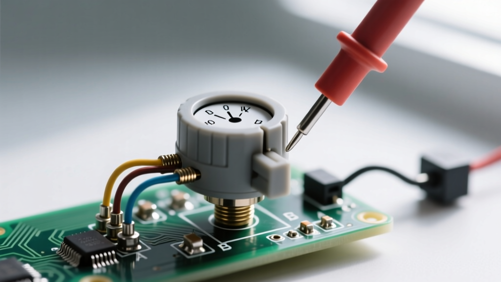
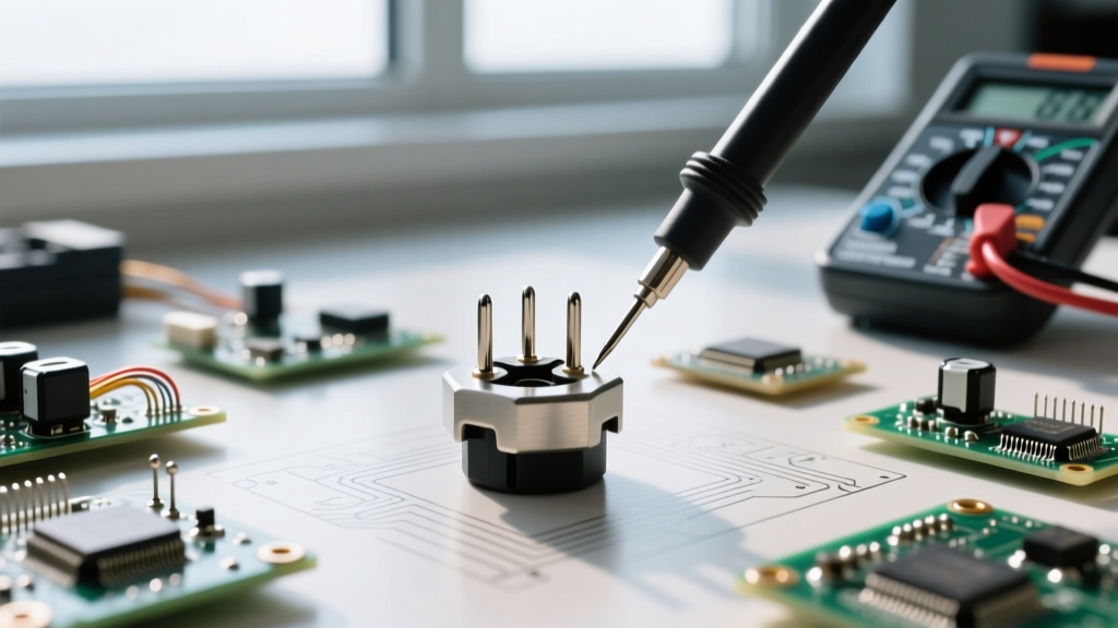
A standard 3 pin potentiometer features two fixed terminals (the ends of the resistive track) and one wiper terminal. To identify the pins and verify the total resistance:
- Set your DMM to the appropriate Ohms range (or auto-ranging).
- Place probes on Pin 1 and Pin 3. The reading should match the component's nominal resistance (e.g., 10kΩ) within the manufacturer's stated tolerance (typically ±10% to ±20% for carbon, ±5% for cermet).
- Rotate the shaft fully clockwise and counter-clockwise. The end-to-end resistance must remain perfectly stable. Any fluctuation indicates internal track damage or broken solder lugs.
Wiper Continuity and Dead-Zone Mapping
Move one probe to the center pin (the wiper, usually Pin 2). As you rotate the shaft from one extreme to the other, the resistance between Pin 1 and Pin 2 should sweep smoothly from near 0Ω to the total nominal resistance. Conversely, the resistance between Pin 2 and Pin 3 will sweep in the opposite direction. According to All About Circuits, the sum of the resistance from Pin 1-to-2 and Pin 2-to-3 must always exactly equal the total end-to-end resistance at any given shaft position.
Measurement Insight: Pay close attention to the extreme ends of the rotation. A high-quality 3 pin potentiometer will read less than 2Ω at the mechanical stops. If you measure 10Ω or higher at the extremes, the wiper is suffering from oxidation or the track has a 'dead zone' due to physical wear.
Phase 2: Dynamic Taper Analysis
The 'taper' defines the mathematical relationship between shaft rotation and resistance change. Verifying the taper is crucial, as misidentifying an Audio taper for a Linear taper will ruin the user experience in voltage-controlled applications.
- Linear Taper (Marked 'B') Resistance changes at a constant rate. At exactly 50% mechanical rotation, the wiper should read 50% of the total resistance (e.g., 5.0kΩ on a 10kΩ pot).
- Audio/Logarithmic Taper (Marked 'A') Designed to match human hearing perception. At 50% rotation, the resistance typically reads between 15% and 20% of the total value (e.g., 1.5kΩ to 2.0kΩ on a 10kΩ pot).
- Reverse Audio Taper (Marked 'C') The inverse of the audio taper. At 50% rotation, expect to read 80% to 85% of the total resistance.
To accurately test the taper, use a DMM with a 'Relative' (REL) or 'Null' function to zero out your test lead resistance, which can otherwise introduce a 5% error on low-impedance wiper measurements.
Phase 3: Advanced CRV Testing with an Oscilloscope
The most insidious failure mode of a 3 pin potentiometer is wiper noise, technically defined as Contact Resistance Variation (CRV). This occurs when the wiper momentarily loses microsecond contact with the resistive track during rotation, causing voltage spikes or 'pops' in an audio circuit, or data glitches in an analog-to-digital converter (ADC) input.
Why DMMs Miss Wiper Noise
A standard handheld DMM samples at a rate of 2 to 4 Hz. If a wiper experiences a 50-microsecond dropout while you rotate the shaft, the DMM will completely miss it, displaying a perfectly smooth resistance transition. To capture CRV, you must use an oscilloscope with a high sampling rate, as recommended in Tektronix application notes on oscilloscope specifications.
Oscilloscope Test Fixture Setup
To measure CRV according to IEC 60393-1 standards, construct the following test circuit:
- Apply a clean, low-noise DC reference voltage (e.g., 5.000V from a linear bench supply) across Pin 1 and Pin 3.
- Connect a 10x passive oscilloscope probe to Pin 2 (the wiper). Ensure the probe ground is tied to the low-side of the DC supply.
- Set the oscilloscope to DC coupling, 1V/div vertical scale, and a fast timebase (e.g., 10µs/div).
- Enable peak-detect or high-resolution acquisition mode to catch nanosecond transients.
- Rotate the shaft slowly and continuously through its full mechanical range.
Interpreting the Waveform: A healthy conductive plastic potentiometer (like the Bourns 3590 series) will show a smooth, straight diagonal voltage ramp from 0V to 5V. A degraded carbon composition pot will display 'fuzz' or high-frequency hash on the trace. A severely worn cermet trimpot (such as a heavily used Bourns 3296W) will show massive vertical spikes, indicating total microsecond wiper disconnects where the voltage momentarily floats.
Diagnostic Matrix: Failure Modes and Measurement Signatures
Use the following matrix to diagnose specific physical failures based on your testing and measurement data.
| Failure Mode | DMM Signature | Oscilloscope Signature | Root Cause & Material Context |
|---|---|---|---|
| Track Wear | Jumping values at specific rotational angles | Repetitive voltage dropouts at the same physical shaft position | Physical abrasion of carbon or cermet track from thousands of mechanical cycles. |
| Wiper Oxidation | High baseline resistance at mechanical stops (>10Ω) | Low-frequency noise floor elevation across the entire sweep | Environmental humidity causing galvanic corrosion on the metal wiper fingers. |
| Solder Joint Fatigue | Intermittent open-circuit (OL) when wiggling the component | Massive, chaotic voltage spikes when physical pressure is applied | Thermal cycling or mechanical stress cracking the lug-to-track internal weld. |
| Moisture Ingress | End-to-end resistance reads lower than nominal value | Non-linear, erratic tracking that drifts over time | Water or flux residue creating parallel leakage paths across the resistive element. |
Material Science: How Track Composition Dictates Test Results
Understanding the material inside your 3 pin potentiometer is vital for interpreting your test results. Carbon composition tracks are inexpensive but exhibit high CRV and poor temperature coefficients (often ±1000 ppm/°C). If you are testing a carbon pot with an oscilloscope, expect a noisy trace even on a brand-new component.
Conversely, wirewound potentiometers offer incredible precision and low CRV, but their resolution is limited by the physical spacing of the wire turns. When sweeping a wirewound pot with an oscilloscope, you will not see a smooth line; you will see a 'staircase' waveform as the wiper jumps from one wire turn to the next. This is not a defect; it is a fundamental characteristic of the topology.
Expert Troubleshooting Tip: Never attempt to clean a sealed 3 pin potentiometer with aggressive solvents like acetone or standard WD-40. These chemicals will dissolve the internal lubricants applied to the wiper track during manufacturing, leading to rapid mechanical failure and catastrophic CRV spikes. If an open-frame carbon track requires cleaning, use only high-purity (99.9%) isopropyl alcohol and a lint-free swab, followed by a specialized conductive contact lubricant like DeoxIT FaderLube.
Conclusion
Testing a 3 pin potentiometer requires moving beyond simple continuity checks. By combining static DMM measurements for taper and dead-zone verification with dynamic oscilloscope analysis for CRV, you can accurately predict the reliability and noise performance of your variable resistors. Whether you are designing a high-fidelity audio mixer or a precision DC-DC converter feedback network, rigorous measurement protocols ensure your prototypes survive the transition from the breadboard to the real world.