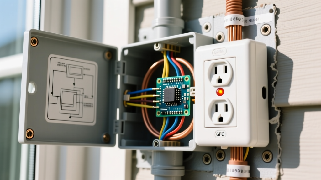
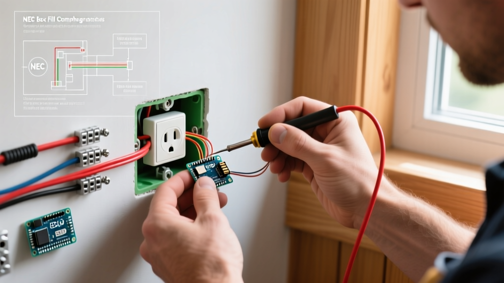
Wiring an outlet switch combo (a single-gang device with a toggle switch and a duplex receptacle) is one of the most practical upgrades you can make in a kitchen, workshop, or basement. The most common and useful configuration is switch controls a separate light fixture, while the receptacle remains always hot. This requires a 3-wire setup (hot, neutral, ground) at the switch box, a 15A or 20A rated combo device, and precise termination of line, load, and neutral wires.
In this guide, we will walk through the exact termination sequence for a standard screw-terminal combo device (like the Leviton 5224-W), assuming power enters the switch box first and then travels to the light fixture. We will also cover the exact meter readings you need to verify a safe, code-compliant installation.
Mains Safety & Prerequisites
Working with 120V AC mains can be fatal. Before opening any junction box, you must:
- De-energize the circuit at the main breaker panel and apply a lockout/tagout device if possible.
- Verify dead using a Non-Contact Voltage Tester (NCVT) on the outside of the wall plate.
- Double-verify dead with a digital multimeter set to AC Volts, probing between the black (hot) and white (neutral) wires, and black to bare (ground). You must read 0.0V before touching any bare copper.
NEC-style guidance: Your local Authority Having Jurisdiction (AHJ) has final authority. If you are unsure about your box fill capacity or lack a neutral wire at the switch location, consult a licensed electrician.
Prerequisite Check: Per NEC 404.2(C), switch boxes controlling lighting loads must have a neutral conductor available. This is perfect for combo devices, as the receptacle requires a neutral to function. If your switch box only has a 2-wire cable (black, white, bare) going up to the light, and the white wire is being used as a switched hot (common in pre-1980s wiring), you cannot install an always-hot receptacle here without pulling a new 3-wire cable.
Tools and Materials List
Single-gang boxes get crowded fast. Using the right connectors and a deep box is the difference between a clean install and a crushed wire fault.
- Device: Leviton 5224-W or Eaton 47015 (15A, 125V, switch controls separate light, outlet always hot). Cost: ~$6 - $9.
- Wire: 14/2 NM-B (for 15A circuits) or 12/2 NM-B (for 20A circuits). Ensure your device rating matches the breaker. If on a 20A breaker, you must use a 20A-rated combo device (e.g., Leviton 5244-W).
- Box: Deep single-gang box (e.g., Carlon B618R-UPC, 22 cubic inches) to accommodate pigtails and the deep device yoke.
- Connectors: Wago 221 2-port and 3-port lever nuts (ideal for tight single-gang pigtailing).
- Strippers: Klein Tools 11055 (for precise 3/4" strip lengths without nicking copper).
- Testers: Fluke 2AC NCVT and a standard digital multimeter (DMM).
- Driver: Phillips #2 screwdriver (hand-tighten; do not use an impact driver on device terminals).
Step-by-Step Wiring Instructions
The following steps assume a standard scenario: Power (Line) enters the switch box, and a second cable (Load) exits the switch box to the light fixture. You will have two black wires, two white wires, and two bare copper grounds in the box.
- Prepare the Wires: Strip exactly 3/4 inch (19mm) of insulation from all solid copper conductors. Fold the bare copper grounds back and strip them to 3/4 inch as well. If using stranded THHN in conduit, twist the strands tightly and tin them with solder or use ferrules to prevent fraying under the screw heads.
- Bond the Grounds: Connect the incoming bare ground wire and the outgoing bare ground wire using a Wago lever nut or wire nut, adding a 6-inch 14 AWG bare copper pigtail. Terminate the other end of this pigtail to the Green ground screw on the combo device. Note: If you are using a metal junction box, you must also pigtail a second ground wire to the box's internal grounding clip or 10-32 ground screw.
- Pigtail the Neutral (White): The receptacle needs a neutral, and the light fixture needs a neutral. Connect the incoming white wire, the outgoing white wire (to the light), and a 6-inch white pigtail together in a 3-port Wago connector. Terminate the other end of the white pigtail to the Silver terminal screw on the receptacle side of the combo device.
- Terminate the Line Hot (Black): Identify the incoming power black wire (the one you verified as hot before de-energizing). Connect this wire directly to the Brass terminal screw marked "Line" or "Hot" on the switch side of the device. Wrap the wire clockwise around the screw so that tightening the screw pulls the loop closed.
- Terminate the Switched Hot (Load): Take the black wire that travels up to the light fixture. Connect this wire to the Black terminal screw (or the second brass screw marked "Load") on the switch side of the device. When you toggle the switch, this terminal will energize, sending 120V to the light.
- Fold and Mount: Carefully fold the wires into the back of the box. Push the grounds in first, then the neutrals, and finally the hots. Keep the Wago connectors flat against the back wall. Align the device yoke with the box ears and drive the mounting screws. Use a torpedo level to ensure the toggle is perfectly plumb before tightening the wall plate.
Terminal Mapping Quick-Reference
| Wire Function | Wire Color | Device Terminal / Screw Color |
|---|---|---|
| Ground | Bare Copper / Green | Green Screw |
| Neutral (Shared) | White | Silver Screw (Receptacle side) |
| Line Hot (Incoming) | Black | Brass Screw (Switch side) |
| Switched Hot (To Light) | Black (or Red) | Black Screw / Load Brass (Switch side) |
Verification and Testing
Never skip the verification step. A miswired neutral can energize the ground plane, creating a severe shock hazard.
- Re-energize the breaker at the panel.
- Test Receptacle Voltage: Set your DMM to AC Volts (V~). Insert the probes into the receptacle slots (hot to neutral). You should read between 114V and 126V (nominal 120V).
- Test Neutral-Ground Bond: Measure from the neutral slot to the ground U-slot. You should read less than 1.0V (ideally 0.1V - 0.3V). If you read 120V here, your neutral and hot are swapped, or the neutral pigtail is disconnected. De-energize immediately and re-check Step 3.
- Test Switch Logic: Toggle the switch. The connected light fixture should turn on and off. The receptacle voltage should remain steady at 120V regardless of the switch position.
The Most Common Botch (and How to Fix It)
The Botch: The "Broken Tab" Confusion.
On a standard duplex receptacle, if you want to make it "half-hot" (one plug switched, one plug always hot), you must snap off the brass connecting fin between the two hot screws.
The Symptom: DIYers often buy the wrong combo device—like the Leviton 5225 (designed so the switch controls the receptacle)—and try to use it to control a separate light. Alternatively, they buy the correct device (5224) but spend 10 minutes looking for a brass tab to break with needle-nose pliers, assuming it works like a standard receptacle.
The Fix: Combo devices designed to control a separate light (like the 5224) have no internal brass tab connecting the switch and the receptacle; they are already internally isolated. If your switch is turning your receptacle on and off instead of your ceiling light, you have the wrong device model. Swap it for a "switch controls light" model, and ensure your Line Hot is on the switch terminal, not jumpered to the receptacle.
Frequently Asked Questions
How do I wire an outlet switch combo so the switch controls the bottom receptacle?
If your goal is to have the toggle switch turn the receptacle on and off (common for living room lamps where the wall switch controls a half-hot outlet), you need a different device, such as the Leviton 5225. In this configuration, you do not need a separate load wire going to a light. You wire the incoming Line Hot to the brass screw, the Neutral to the silver screw, and the Ground to the green screw. The internal jumper handles the rest, routing power through the switch and down to the receptacle. Always verify the manufacturer's wiring diagram on the back of the device box, as internal jumper configurations vary by brand.
What wire gauge and breaker size should I use for a switch outlet combo?
The wire gauge and breaker must match the device rating and the circuit's total load. Most standard combo devices are rated for 15 Amps. Therefore, they should be installed on a 15A breaker using 14 AWG copper wire. If you are installing the combo on a kitchen or garage 20A circuit (which uses 12 AWG wire), NEC 210.21(B)(3) generally requires the receptacle to be rated for 20A if it is a single receptacle on the circuit. Because a combo device is technically a duplex (multiple receptacles), a 15A device is legally permissible on a 20A circuit in many jurisdictions, but best practice—and the safest route—is to buy a 20A-rated combo device (like the Leviton 5244-W) and use 12 AWG wire to match the breaker.
Why does my GFCI breaker trip immediately when I turn on the switch?
If your combo device is on a GFCI-protected circuit and trips the moment you toggle the switch to turn on the light, you likely have a shared neutral fault or a ground fault at the fixture. GFCI devices measure the exact current leaving on the hot wire and returning on the neutral wire. If the neutral returning from the light fixture is accidentally pigtailed to a neutral from a different circuit, or if it bypasses the GFCI's sensing coil, the GFCI will see an imbalance and trip. Ensure that the neutral returning from the light fixture connects only to the neutral pigtail going directly back to the combo device's silver terminal, and nowhere else.