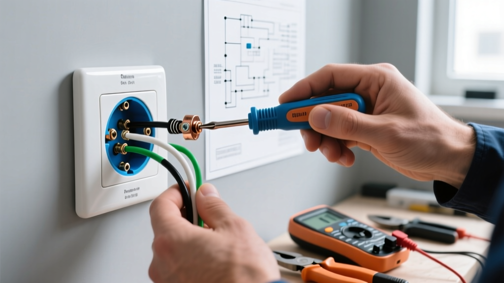
The Direct Answer: How to Wire a Switch Loop (Power at Light)
When you are wiring light switch power at light—commonly called a "switch loop"—the main power feed enters the ceiling junction box first, and a separate cable drops down to the wall switch. Under current NEC 404.2(C) requirements, you can no longer use a standard 2-wire cable for new installations. You must run a 3-wire cable (14/3 or 12/3 NM-B) to provide a neutral at the switch box for modern smart switches and timers.
The quick color code: The black wire drops down as the always-hot. The red wire returns to the ceiling as the switched-hot. The white wire runs down as the neutral and is capped at the switch. At the ceiling, line black connects to cable black; line white, cable white, and fixture white bundle together; and cable red connects to fixture black.
Tools, Materials, and Device Ratings
Do not guess your wire gauge. The cable size is strictly dictated by the breaker protecting the circuit. Using 14 AWG on a 20A breaker is a severe fire hazard.
Required Tools
- Voltage Tester: Klein NCVT-3 (non-contact) and a CAT III digital multimeter (e.g., Fluke 117) for definitive dead-front verification.
- Wire Strippers: Klein 11055 (for 10-18 AWG solid copper).
- Lineman Pliers: For twisting solid copper conductors before nutting.
Materials & Ratings
- For 15A Circuits: 14/3 NM-B (Romex) cable. Switch rating: 15A, 120V AC.
- For 20A Circuits: 12/3 NM-B cable. Switch rating: 20A, 120V AC.
- Wire Connectors: Ideal 34 Yellow wire nuts (rated for three 14 AWG or 12 AWG wires) or Wago 221 lever nuts (3-port) for foolproof terminations.
- Switch: Standard single-pole toggle or smart switch requiring a neutral.
Mains Safety Protocol (Do Not Skip)
- Turn off the specific breaker at the main panel. Do not rely solely on the wall switch.
- Apply a lockout/tagout device to the breaker panel if others are in the home.
- Test your multimeter on a known live outlet to prove the meter works.
- Test the target wires at the ceiling box (Black to White, Black to Ground). The meter must read 0.0V.
- Local codes may require a licensed electrician for new circuit runs; this guide assumes NEC-style guidance for DIY branch circuit modifications.
Step-by-Step: Terminating the Switch Loop
Strip 3/4 inch of insulation from all individual conductors. Ensure no bare copper is exposed outside the wire nuts or switch terminals.
Phase 1: The Ceiling Junction Box
- Grounds First: Twist the bare copper ground from the power feed, the bare copper from the 14/3 switch drop, and the green/bare ground wire from the light fixture together. Secure with a green wire nut or Wago lever nut.
- The Neutral Bundle: Connect the White wire from the power feed, the White wire from the light fixture, and the White wire from the 14/3 switch cable. This passes the neutral through to the switch box. Secure with a yellow wire nut.
- The Always-Hot Drop: Connect the Black wire from the power feed directly to the Black wire of the 14/3 switch cable. This sends unswitched 120V down to the wall.
- The Switched-Hot Return: Connect the Red wire from the 14/3 switch cable to the Black wire of the light fixture. This completes the circuit when the wall switch closes.
Phase 2: The Wall Switch Box
- Ground the Switch: Connect the bare copper ground wire to the Green ground screw on the bottom of the switch.
- Cap the Neutral: The White wire is your neutral. Standard single-pole switches do not use it. Cap it with a wire nut and tuck it into the back of the box. (If using a smart switch, connect this white wire to the switch's neutral terminal).
- Terminate the Hots: Connect the Black wire (always-hot) to the top brass screw on the switch. Connect the Red wire (switched-hot) to the bottom brass screw. (Note: On a standard single-pole switch, the brass screws are interchangeable; line/load orientation does not matter. Do NOT use the black/dark screws, which are for 3-way setups).
Decision Path: Choosing Your Cable and Switch
Use this decision matrix to lock in your exact materials before heading to the hardware store. Do not mix 14 AWG and 12 AWG on the same branch circuit.
| Scenario | Breaker Size | Required Cable | Concrete Device Pick |
|---|---|---|---|
| Standard Lighting (Most Common) | 15 Amp | 14/3 NM-B | Leviton 1451-2W (15A Toggle) |
| Kitchen/Bath/Receptacle Circuit | 20 Amp | 12/3 NM-B | Leviton 5252-W (20A Toggle) |
| Smart Switch / Dimmer / Timer | 15A or 20A | 14/3 or 12/3 NM-B | Lutron Caseta PD-5S-DV |
The Default Pick: If you are replacing an old 14/2 switch loop in a standard bedroom or hallway on a 15A breaker, buy 14/3 NM-B cable and a Leviton 1451-2W 15A switch. This guarantees NEC compliance and future-proofs the box for smart home upgrades.
Verify and Test: Meter Readings
Before pushing the wires back into the boxes and mounting the fixtures, you must verify the circuit logic. Re-energize the breaker and use your CAT III multimeter set to AC Voltage (V~).
- Test 1 (Ceiling Box Hot): Probe the Line Black and Line White. Expected reading: 114V to 126V.
- Test 2 (Switch Box Hot): Probe the Cable Black and Cable White at the wall. Expected reading: 114V to 126V. (This proves your always-hot drop and neutral are intact).
- Test 3 (Switch Logic OFF): With the switch in the OFF position, probe across the two brass screws. Expected reading: ~120V. (The meter is reading the potential difference across the open gap).
- Test 4 (Switch Logic ON): Flip the switch ON and probe across the two brass screws. Expected reading: 0.0V to 0.2V. (The closed switch creates a continuous path, eliminating the voltage drop across the terminals).
If Test 3 and 4 are reversed, your switch is wired backwards or you have a short. De-energize immediately and re-check your red/black terminations.
The Most Common Botch (And How to Spot It)
The most dangerous mistake when wiring light switch power at light is the "Switched Neutral" botch. This happens when a DIYer sends the always-hot (black) directly to the light fixture's black wire, and uses the switch to break the white neutral wire instead of the hot.
The Physics: Because the switch is breaking the neutral return path rather than the hot supply, the light socket shell remains energized at 120V relative to ground. Your body becomes the path of least resistance to ground when you touch the bulb base. Always ensure the black/switched-hot is the wire being interrupted by the switch, never the white neutral. Refer to OSHA electrical safety guidelines for more on shock hazards in residential wiring.
Another frequent error is using 14/2 NM-B cable for new work, leaving no neutral at the switch box. While this was legal prior to 2011, it violates modern NEC 404.2(C) and will fail a rough-in inspection. It also forces you to buy expensive "no-neutral" smart switches (which often cause LED flickering) when you eventually upgrade to home automation. Run the 3-wire cable the first time and do it right.