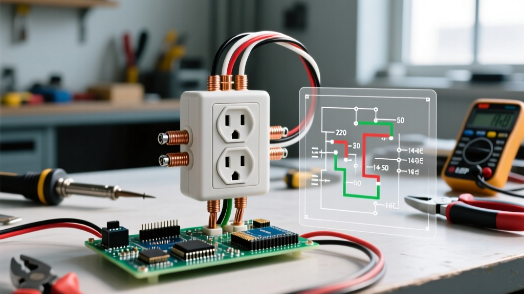
Finding only two wires in a wall box when you are trying to install a switch/outlet combo device is one of the most common points of confusion in DIY home electrical work. A combo device—like the widely used Leviton 5245-W (15A) or 5645-W (20A)—combines a single-pole toggle switch and a standard duplex receptacle into a single-gang footprint. But the physical wires inside your wall box dictate strict limitations on what that device can actually do.
If your box contains only two current-carrying wires (one black hot, one white neutral) plus a bare or green ground, the switch must be used to control the outlet itself. You cannot use this 2-wire setup to keep the outlet always-on while using the switch to control a remote ceiling light. Doing so requires a third wire to carry the switched-hot feed to the light fixture. This guide provides the exact terminal mappings, device sizing, and testing procedures to wire a 2-wire combo device safely and correctly.
The 2-Wire Reality Check: What You Can (and Cannot) Do
Before stripping any wire insulation, you must understand the circuit topology. According to Kirchhoff’s Current Law, current must have a complete path from the source, through the load, and back to the neutral. In a standard 2-wire cable (like 14/2 or 12/2 NM-B), you have exactly one ungrounded conductor (hot) and one grounded conductor (neutral).
If you want the outlet to remain always-on while the switch controls a remote light, you need an always-hot feed for the receptacle, a switched-hot feed for the light, and a shared neutral. That requires three wires in the box. With only two wires, the single hot wire must feed the switch first, and the switch's output feeds the receptacle.
| Wires in Box | Wire Colors Present | Switch Function | Outlet Function | Remote Light Control? |
|---|---|---|---|---|
| 2 Wires | Black (Hot), White (Neutral) | Controls the receptacle | Switched (Turns on/off with switch) | No (Impossible without 3rd wire) |
| 3 Wires | Black (Always-Hot), Red (Switched-Hot), White (Neutral) | Controls remote light | Always-On | Yes |
| 3 Wires (Alternate) | Black (Hot), White (Neutral), Red (Traveler/Feed) | Controls half-receptacle | Half-Switched, Half Always-On | No |
| 4 Wires | Black (Line), Red (Load to Light), White (Neutral), Black (Feed to next box) | Controls remote light | Always-On (via daisy-chain) | Yes |
Tools, Materials, and Device Sizing
Matching your wire gauge to the correct breaker and device rating is a strict requirement under NEC Article 210.21. Installing a 15A-rated combo device on a 20A breaker is a severe fire hazard, as the device's internal contacts can overheat and melt before the breaker trips.
| Incoming Wire Gauge (Copper) | Breaker Size | Required Device Rating | Example Combo Model | Terminal Screw Torque |
|---|---|---|---|---|
| 14 AWG | 15 Amp | 15A / 125V | Leviton 5245-W | 12 in-lbs (1.0 Nm) |
| 12 AWG | 20 Amp | 20A / 125V | Leviton 5645-W | 14 in-lbs (1.2 Nm) |
| 12 AWG | 15 Amp | 15A or 20A (Both acceptable) | Leviton 5245-W or 5645-W | 12 to 14 in-lbs |
Required Tools & Materials
- Combo Device: Leviton 5245-W (15A) or 5645-W (20A), matching your wire gauge.
- Wire Strippers: Klein Tools 11055 (for 14/12 AWG solid copper).
- Voltage Tester: Non-contact voltage tester (NCVT) and a digital multimeter (DMM) or solenoid tester (Wiggy).
- Screwdrivers: #2 Robertson (square) and #2 Phillips, ideally with an insulated shaft.
- Jumper Wire: One 4-inch piece of 14 AWG or 12 AWG solid copper (matching circuit gauge) with a green or bare ground pigtail if the box is metal.
- Tape: Yellow or red electrical tape (for marking the hot wire if re-identifying is needed, though not required for this specific 2-wire setup).
Mains Safety and Box Verification
Working on branch circuits involves 120V AC, which is lethal. You must de-energize the circuit at the main service panel before opening the wall box. Turn off the breaker, apply a lockout/tagout device if possible, and verify the circuit is dead using a tested multimeter or NCVT. Never rely solely on a wall switch being in the "OFF" position. If you are unsure which breaker controls the box, use a circuit breaker finder or turn off the main breaker. Local codes may require a licensed electrician for this work; this guide serves as NEC-style educational guidance.
- De-energize: Flip the corresponding 15A or 20A breaker to the OFF position.
- Verify Dead (NCVT): Place your non-contact voltage tester against the existing switch faceplate and into the gaps. It should remain silent/unlit.
- Verify Dead (Multimeter): Remove the faceplate. Set your DMM to AC Voltage (V~). Place one probe on the bare ground wire and the other on the black wire terminal. The reading must be 0.0V.
- Inspect the Box: Confirm you have exactly one black wire, one white wire, and one bare/green ground wire entering the box. If you see a red wire, a second black wire, or a bundle of whites, stop—this is not a simple 2-wire setup.
Step-by-Step Wiring: Switch Controlling the Receptacle
The anatomy of a standard combo device features a Black screw (Line/Hot input), two Brass screws (Switch Load and Receptacle Hot), two Silver screws (Neutrals), and a Green screw (Ground). The critical feature for a 2-wire setup is the brass break-off fin (tab) connecting the two brass screws.
- Prep the Wires: Use the stripping gauge on the back of the combo device to strip exactly 5/8-inch of insulation from the black, white, and bare ground wires. Do not nick the copper conductor; if you do, snip and re-strip.
- Inspect the Brass Fin (CRITICAL): Look at the brass side of the Leviton device. You will see a small metal fin connecting the two brass screws. Leave this fin completely intact. Do not break it off with pliers. This fin is the internal bridge that allows the switch to send power to the outlet.
- Land the Ground: Form a J-hook on the bare copper ground wire. Hook it clockwise around the Green grounding screw on the device. Tighten firmly. (If using a metal box, you must also attach a ground pigtail to the box's ground clip or threaded hole).
- Land the Neutral: Form a J-hook on the White neutral wire. Hook it clockwise around one of the Silver screws on the outlet side of the device. Tighten to roughly 12 in-lbs. The second silver screw will remain empty.
- Land the Hot (Line): Form a J-hook on the Black hot wire. Hook it clockwise around the Black screw (often marked "LINE" or featuring a black phillips head). This screw feeds the internal switch mechanism. Tighten securely.
- Check the Brass Screws: Because the brass fin is intact, and no remote light is being controlled, the two Brass screws remain empty. The internal switch mechanism will route power from the Black screw, through the toggle, and out through the intact brass fin to the receptacle's internal hot bus.
- Fold and Mount: Carefully fold the wires into the back of the box. Push the ground wire deep into the back, followed by the neutral and hot wires. Align the device strap with the box ears and secure with the provided 6-32 mounting screws.
The Most Common Botch (And How to Fix It)
The single most frequent mistake DIYers make when wiring a 2-wire combo device is breaking the brass fin or misidentifying the Line and Load screws.
The Symptom: You turn the breaker back on. The toggle switch clicks satisfyingly, but the receptacle is completely dead. A lamp plugged into the outlet does not turn on.
The Cause: Many online tutorials for wiring standard duplex outlets instruct you to "break the tab" to create a split-receptacle (where the top half is switched and the bottom is always-on). If you blindly apply this advice to a 2-wire combo device and snap off the brass fin, you sever the internal bridge between the switch output and the receptacle hot bus. The switch will click, but power has no physical path to reach the outlet slots.
The Fix: Turn the breaker off, verify dead, and pull the device back out. Inspect the brass side. If the fin is broken, the device is permanently ruined for a 2-wire application. You cannot solder or jumper it reliably due to the tight spacing and UL listing requirements. You must discard the device and purchase a new Leviton 5245-W or 5645-W, ensuring the fin remains intact during installation.
Verify and Test: Expected Meter Readings
Never assume a wiring job is correct just because the breaker didn't trip. You must verify the voltage states under both switch conditions to ensure the internal contacts are seating properly and the circuit is safe.
| Switch State | DMM Probe Placement | Expected Reading (VAC) | Meaning / Action Required |
|---|---|---|---|
| OFF | Hot Slot (Short blade) to Neutral Slot (Long blade) | 0.0V | Correct. Switch is interrupting the hot path. |
| ON | Hot Slot (Short blade) to Neutral Slot (Long blade) | 114V - 126V | Correct. Nominal 120V is reaching the load. |
| ON | Hot Slot to Ground Slot (U-shape) | 114V - 126V | Correct. Equipment grounding path is intact. |
| OFF | Hot Slot to Ground Slot (U-shape) | 0.0V | Correct. No voltage leakage to ground. |
| ON or OFF | Neutral Slot to Ground Slot | < 2.0V | Correct. Normal minor voltage drop. If >2V, check for loose neutral at panel. |
Set your digital multimeter to AC Voltage. Insert the probes into the receptacle slots as indicated in the matrix above. If your switch is ON but you read 0V across the Hot and Neutral slots, re-verify that the black wire is landed on the Black screw (not a brass screw) and that the brass fin was not accidentally damaged during insertion into the box. Once all readings match the expected values, secure the faceplate and restore full power to the room.