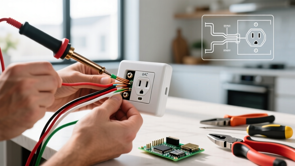
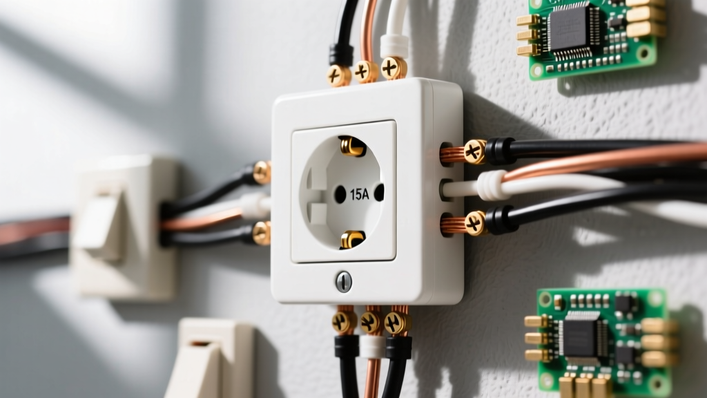
To wire an outlet and switch in the same box where the switch controls a separate light fixture and the receptacle remains always-hot, you must pigtail the incoming hot (black) wire to both the switch's brass terminal and the receptacle's brass terminal. All neutral (white) wires are spliced together and pigtailed to the receptacle's silver terminal. The bare copper grounds are bonded to the metal box (if applicable) and both devices. This setup requires a deep single-gang box (minimum 22 cubic inches) to satisfy NEC box fill calculations.
⚠️ Mains Voltage Safety Protocol
Working inside an electrical box involves lethal 120V/240V AC mains voltage. Before opening any junction box or receptacle enclosure, de-energize the circuit at the main breaker panel. Apply a lockout/tagout (LOTO) device if others are in the home. Verify the circuit is dead using a Non-Contact Voltage Tester (NCVT), then confirm with a digital multimeter set to AC Volts by testing between the black and white wires, and black to ground. If your meter reads anything above 1V, stop immediately. Local codes (NEC-style guidance) may require a licensed electrician for new circuit runs; your local AHJ has final authority.
Terminal Mapping and Box Fill Specifications
Before stripping a single wire, you must verify your box volume and understand exactly where each conductor terminates. The most frequent reason this specific installation fails inspection is a box fill violation. A standard 18-cubic-inch single-gang box is too small for a switch and a receptacle on the same yoke or in the same 1-gang enclosure.
Wire Color to Terminal Mapping
This table assumes a standard 15A circuit using 14 AWG copper NM-B cable. The switch controls a downstream light, while the receptacle provides continuous power.
| Wire Color / Function | Device Termination | Screw Color & Location | Notes |
|---|---|---|---|
| Incoming Hot (Black) | Switch & Receptacle | Brass (via pigtail) | Must be split using a wire nut and two 6-inch pigtails. |
| Switched Leg (Red or Black w/ tape) | Switch | Brass (opposite side) | Carries power to the light fixture only when switch is ON. |
| Incoming Neutral (White) | Receptacle | Silver | Spliced with the light fixture's neutral; pigtailed to receptacle. |
| Light Fixture Neutral (White) | Splice only | N/A (Wire Nut) | Never lands on the switch. Switches do not use neutral wires (unless smart). |
| Equipment Ground (Bare Copper) | Switch, Receptacle, Box | Green | All grounds spliced together; pigtailed to metal box and both devices. |
NEC Box Fill Calculation (14 AWG / 15A Circuit)
According to NFPA 70 (NEC) Article 314.16, every item in the box consumes volume. For 14 AWG wire, each 'allowance' equals 2.0 cubic inches.
| Item in Box | NEC Allowances | Volume (14 AWG) |
|---|---|---|
| 4 Current-Carrying Conductors (2 in, 2 out) | 4 | 8.0 cu in |
| Switch (counts as 2) | 2 | 4.0 cu in |
| Receptacle (counts as 2) | 2 | 4.0 cu in |
| All Grounding Conductors (counts as 1 total) | 1 | 2.0 cu in |
| Internal Cable Clamps (counts as 1 total) | 1 | 2.0 cu in |
| TOTAL REQUIRED | 10 | 20.0 cu in |
Takeaway: A standard 18 cu in single-gang box will fail. You must use a deep single-gang box (like the Carlon B618R-UP at 22 cu in) or step up to a 2-gang box.
Tools and Materials List
Do not substitute device ratings. A 20A circuit requires a 20A receptacle (identified by the T-shaped neutral slot), though the switch can remain 15A. This guide assumes a standard 15A branch circuit.
- Wire: 14/2 NM-B (Romex) for 15A circuits. Ensure it is copper, not aluminum.
- Receptacle: 15A Tamper-Resistant (TR) duplex receptacle (e.g., Leviton R72-05320-2WS).
- Switch: 15A Single-Pole AC Quiet Toggle or Decora Rocker (e.g., Leviton R72-05603-2WS).
- Box: 22+ cubic inch deep single-gang PVC or metal box.
- Connectors: Ideal 33 (Yellow) or 34 (Tan) wire nuts; Wago 221 lever nuts (optional but excellent for tight boxes).
- Pigtails: 6-inch lengths of 14 AWG solid THHN (Black, White, Bare) or scrap 14/2 NM-B.
- Tools: Wire strippers (calibrated for 14 AWG), lineman's pliers, Phillips #2 screwdriver, digital multimeter, NCVT.
Step-by-Step Wiring Procedure
Follow these steps sequentially. Strip all wire ends to exactly 3/4 inch to ensure no bare copper is exposed outside the terminal, and no insulation is pinched under the screw head.
- Bond the Grounds (Bare Copper): Gather the bare copper ground from the incoming power cable, the bare ground from the switch-loop cable, and a 6-inch bare pigtail. Twist them together and secure with a yellow wire nut. Connect the other end of the pigtail to the green ground screw on the metal box (if using metal). Create a second ground splice with another pigtail to connect to the green screws on both the switch and the receptacle.
- Splice the Neutrals (White): Gather the white neutral from the incoming power, the white neutral returning to the light fixture, and a 6-inch white pigtail. Twist and cap with a wire nut. Connect the free end of the white pigtail to the silver terminal screw on the receptacle. Note: The white wire going to the light fixture does not connect to the switch.
- Pigtail the Incoming Hot (Black): Take the black wire from the incoming power cable and splice it to two 6-inch black pigtails using a wire nut. This splits the always-hot feed.
- Terminate the Receptacle Hot: Connect one of the black pigtails from Step 3 to the brass terminal screw on the receptacle. Do not break the brass fin (tab) between the two brass screws; leave it intact so both top and bottom outlets remain always-hot.
- Terminate the Switch Line: Connect the second black pigtail from Step 3 to one of the brass terminal screws on the single-pole switch. (On a standard single-pole switch, either brass screw can be the 'Line' input).
- Terminate the Switched Leg: Take the black (or red) wire from the cable heading up to the light fixture. If it is black, wrap a band of red electrical tape around the insulation to identify it as a switched leg. Connect this wire to the remaining brass terminal screw on the switch.
- Mount the Devices: Carefully fold the wires in an accordion pattern (grounds in the back, neutrals in the middle, hots on the sides). Push the switch and receptacle into the box. Drive the mounting screws into the box ears. Torque device terminal screws to manufacturer specs (typically 14 in-lbs for 14 AWG on Leviton devices) to prevent thermal loosening.
Verification and Testing
Never assume the wiring is correct just because the breaker didn't trip immediately. Perform these meter readings before plugging in any loads.
- Restore Power: Turn the breaker back on at the panel.
- Test Receptacle Voltage: Set your multimeter to AC Volts (V~). Insert the probes into the receptacle slots (Hot to Neutral). Expected Reading: 114V to 126V (120V nominal). If it reads 0V, check your hot pigtail splice.
- Test Ground Reference: Measure from the Hot slot to the Ground pin. Expected Reading: 120V. Measure from Neutral to Ground. Expected Reading: < 1.0V. If Neutral-to-Ground reads 120V, you have a miswired neutral or an open neutral upstream.
- Test Switch Operation: Turn the switch ON. The downstream light should illuminate. Turn it OFF; the light should extinguish. The receptacle must remain powered regardless of the switch position.
The Most Common Botch: Switched Neutrals and Box Overfill
When wiring an outlet and switch in the same box, DIYers frequently make two critical errors that compromise safety and code compliance.
Botch #1: Switching the Neutral (The Lethal Error)
The Mistake: The installer connects the incoming white (neutral) wire to the switch, and passes the black (hot) wire straight through to the light fixture. The switch breaks the neutral path instead of the hot path.
The Symptom: The light turns on and off normally. However, because the hot wire is continuously connected to the light fixture, the socket remains energized at 120V even when the switch is in the OFF position. If you touch the internal contacts while changing a bulb, you will complete the circuit to ground and receive a severe shock. NEC Article 404.2 explicitly forbids switching the grounded (neutral) conductor for this exact reason.
The Fix: Always ensure the switch interrupts the black (hot) wire. The white wires must bypass the switch entirely and splice directly to the fixture's neutral.
Botch #2: Box Fill Overcrowding
The Mistake: Forcing a switch, a receptacle, and four cables into a standard 18 cubic-inch shallow single-gang box.
The Symptom: The devices refuse to sit flush against the drywall. The drywall screws pinch the wire insulation against the metal yoke of the receptacle, causing a dead short that trips the breaker instantly, or worse, creates a high-resistance fault that melts the terminal lug over time.
The Fix: Use the box fill table provided above. If you are retrofitting an old shallow box, you must cut the drywall and install an 'old work' deep box (minimum 22 cu in) or transition to a 2-gang box with a 2-gang cover plate.