In electronics and circuit theory, a Single Pole Double Throw (SPDT) switch is a fundamental component with one input terminal (the pole) and two output terminals (the throws). When you translate this exact electromechanical design into 120V AC residential wiring, it is universally known as a 3-way switch. Understanding how to wire a single pole double throw switch allows you to control a single lighting load from two separate physical locations, such as the top and bottom of a staircase or at both ends of a hallway.
This guide walks through the exact terminal mappings, wire color assignments, and safety protocols required to install a standard mechanical SPDT (3-way) switch on a 15A or 20A branch circuit using NM-B cable. We will focus on the line-side switch installation, which is where the incoming hot feed enters the circuit.
Tools, Materials, and Device Ratings
Before opening the junction box, ensure your materials match the circuit's ampacity. Using undersized switches on high-draw circuits causes internal contact pitting and eventual thermal failure.
Required Materials & Ratings
- Switch: 15A 120V AC SPDT (3-way) toggle or rocker (e.g., Leviton 5603-2W or Eaton 3W). Use a 20A rated switch if your branch circuit breaker is 20A.
- Cable: 14/3 NM-B (Romex) for 15A circuits; 12/3 NM-B for 20A circuits. The '/3' indicates three insulated conductors plus a bare ground.
- Wire Nuts: Ideal 341 (blue) or 314 (tan) for 14 AWG; Ideal 312 (yellow) for 12 AWG.
- Strippers: Klein 11055 (for 10-18 AWG solid copper).
- Testers: Non-contact voltage tester (NCVT) like the Fluke 2AC, and a digital multimeter (DMM) for verification.
- Tools: Phillips and flathead screwdrivers, lineman's pliers, and electrical tape (black/red for re-identification).
SPDT Terminal and Wire Color Map
The most critical step in learning how to wire a single pole double throw switch is identifying the terminals. Unlike a standard single-pole switch where the two brass screws are interchangeable, an SPDT switch has three distinct current-carrying terminals. Misidentifying the 'Common' terminal is the primary cause of circuit failure.
| Terminal Name | Screw Color / Marking | Wire Color (14/3 NM-B) | Circuit Function |
|---|---|---|---|
| Common (Pole) | Black or Dark Oxidized Brass (Often marked 'COM') | Black (Line Hot) or Black (Load) | The single input (line side) or single output (load side) of the switch. |
| Traveler 1 (Throw A) | Light Brass | Red (Traveler) | One of two alternate paths carrying current to the second switch. |
| Traveler 2 (Throw B) | Light Brass | Black (Traveler from 14/3) | The second alternate path carrying current to the second switch. |
| Ground | Green (or bare metal frame) | Bare Copper | Equipment grounding conductor for fault clearing. |
Note: Standard mechanical SPDT switches do not have a neutral terminal. The white neutral wire from your NM-B cable must bypass the switch entirely and splice straight through to the light fixture.
Mains Safety and Preparation
Working on 120V AC mains requires strict adherence to lockout/tagout procedures.
- Turn off the branch circuit breaker at the main service panel.
- Place a piece of tape over the breaker to prevent accidental re-energization.
- Test your NCVT on a known live circuit (like a plugged-in lamp) to verify the tester works.
- Insert the NCVT into the target junction box and verify the circuit is dead.
- Confirm with a multimeter set to AC Volts: place one probe on the bare ground and the other on the black hot wire. The reading must be 0.0V.
Disclaimer: This guide follows NEC-style best practices. Your local Authority Having Jurisdiction (AHJ) may require a licensed electrician for new circuit runs or panel work.
Step-by-Step Wiring Procedure (Line-Side Switch)
These steps assume you are wiring the first switch in the circuit (the line-side switch), where the main power feed from the breaker panel enters the box, and a 14/3 NM-B cable runs onward to the second (load-side) switch.
- Prepare the Cables: Strip back 3/4 inch of insulation from all conductors using your wire strippers. If using solid THHN in conduit, ensure the wires are straight and free of deep nick marks.
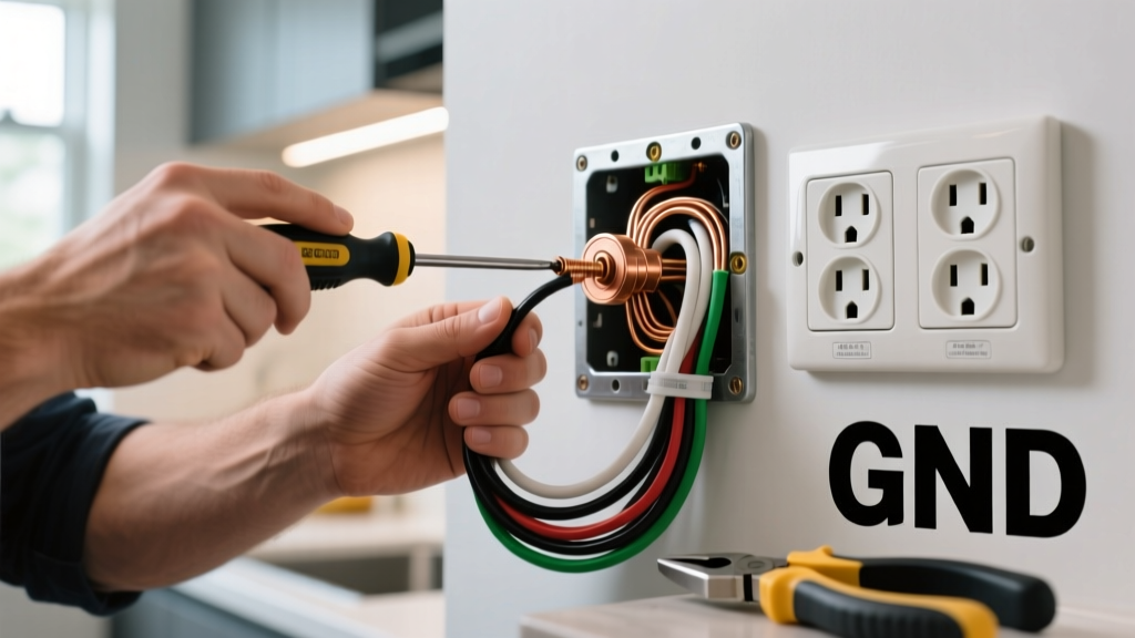
- Terminate the Ground: Create a pigtail using a short piece of bare 14 AWG copper. Wire-nut the pigtail to the incoming bare ground and the outgoing bare ground (from the 14/3 cable). Attach the free end of the pigtail to the Green ground screw on the SPDT switch. Tighten until snug.
- Splice the Neutrals: Take the incoming white neutral wire and the outgoing white neutral wire (from the 14/3 cable). Strip them and join them together with a wire nut. Do not attach the white wire to the switch. Tuck this splice neatly into the back of the junction box.
- Identify the Common Terminal: Locate the black or dark-colored screw on the switch. This is your Common (Pole) terminal.
- Land the Line Hot: Take the incoming Black hot wire from the breaker panel and loop it clockwise around the Common (black) screw. Tighten firmly. The clockwise loop ensures the screw pulls the wire tighter as you torque it down.
- Land the Travelers: Take the Red wire and the Black wire from the outgoing 14/3 NM-B cable. Attach one to each of the two Light Brass (Traveler) screws. The order between the two brass screws does not matter; they are functionally identical throws.
- NEC Re-identification Rule: If your specific cable routing requires using the White wire from a 14/3 cable as a traveler instead of the black wire, NEC Article 200.7(C) mandates that you must wrap the white wire with black or red electrical tape at both termination points to re-identify it as a hot conductor.
- Secure the Device: Carefully fold the wires into the box, ensuring no bare copper is exposed outside the terminal screws. Mount the switch to the box using the provided 6-32 machine screws, and attach the wall plate.
Verification and Testing
Never skip the verification step. Before restoring power to the entire circuit, perform a cold test, followed by a live test.
Cold Test (Power Off)
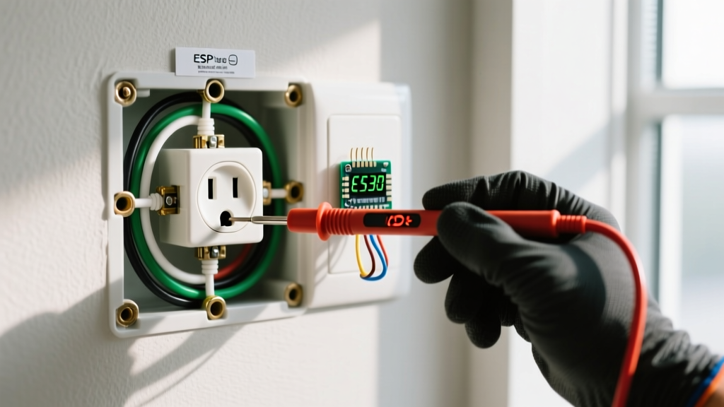
Set your digital multimeter to Continuity (the diode/beep symbol). Place one probe on the Common screw and the other on Traveler 1. Flip the toggle. The meter should beep in one position and show 'OL' (open loop) in the other. Move the probe to Traveler 2 and repeat; the behavior should invert. This confirms the internal mechanical wiper is functioning correctly.
Live Test (Power On)
- Restore power at the breaker panel.
- Set your multimeter to AC Volts (V~).
- Place the black probe on the Common screw and the red probe on the Ground screw. You should read 120V (±5V).
- Move the red probe to Traveler 1. Depending on the toggle position, you will read either 120V or 0V.
- Move the red probe to Traveler 2. You will read the opposite of Traveler 1 (if Traveler 1 was 120V, Traveler 2 will be 0V).
If these readings match, your line-side SPDT switch is wired perfectly. The load-side switch will mirror this setup, but its Common terminal will connect to the black wire leading up to the light fixture.
The Most Common Botch and How to Fix It
When DIYers ask why their newly wired 3-way circuit isn't working, 90% of the time they have committed the Traveler-on-Common swap.
The Symptom: The light will only turn on and off from Switch A if Switch B is held in one specific, static position. If you flip Switch B to the opposite position, Switch A becomes completely dead and unresponsive.
The Cause: The installer assumed the two brass screws and the one black screw were interchangeable, or they failed to identify the incoming line hot wire. They landed a traveler wire on the black Common screw, and the line hot wire on a brass Traveler screw.
The Fix: De-energize the circuit. Remove the switch from the box. Identify the wire that carries constant 120V from the panel (this requires a brief live test with the wires safely separated and capped, or tracing the cable back to the panel). Move that constant hot wire to the Black/Common screw. Move the two wires running to the other switch to the Brass/Traveler screws. For a deeper dive into standard switch configurations, refer to the Leviton switch wiring documentation.
Code, Sizing, and Compatibility Notes
When sizing your SPDT switch, always defer to NFPA 70 (National Electrical Code) Article 404. While a 15A rated switch is legally permitted on a 20A branch circuit under very specific lighting-load exceptions (NEC 404.14), the best practice for longevity and safety is to match the switch rating to the breaker rating. If you have a 20A breaker feeding the circuit with 12 AWG wire, buy a 20A rated SPDT switch. The internal contacts are heavier, reducing arcing and voltage drop over years of mechanical toggling.
Finally, if you are upgrading to smart home automation, standard mechanical SPDT switches are incompatible with most smart 3-way kits. Smart switches require a constant neutral wire at the switch box to power their internal WiFi/Zigbee radios. If your junction box lacks a neutral bundle (common in pre-1985 homes), you will need to look into specific 'no-neutral' smart switches or pull a new neutral wire from the fixture.