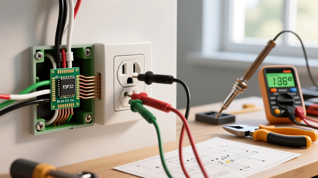
When you are tracing a fault on a control board or wiring a new subpanel, misinterpreting the symbol for switch in circuit diagrams can lead to dead shorts or miswired logic. In North America, the IEEE 315 (NEMA) standard dictates schematic symbols, while Europe and most of the world rely on IEC 60617. The most basic symbol—a single-pole single-throw (SPST) switch—looks like a hinged line breaking a connection in IEEE, but appears as a simple angled line breaking a straight path in IEC. Below is the master reference to keep on your bench.
Master Reference: Switch Symbols by Standard
The table below maps the most common switch symbols to their practical circuit meanings. Use this to translate paper schematics into physical wiring actions.
| Switch Type | IEEE/NEMA (US/NEC) Symbol | IEC 60617 (Global) Symbol | Practical Circuit Meaning |
|---|---|---|---|
| SPST (Single Pole, Single Throw) | Hinged pivot line breaking a single contact point | Angled line breaking a straight conductor path | Basic on/off for a single hot wire (e.g., standard 120V lighting). |
| SPDT (Single Pole, Double Throw) | Single pivot line with two target contact points | Angled line with a forked or dual-contact target | Selects between two paths; the physical equivalent of a residential 3-way switch. |
| DPST (Double Pole, Single Throw) | Two SPST symbols linked by a dashed mechanical line | Two IEC SPST symbols linked by a dashed line | Disconnects two wires simultaneously; critical for breaking both Hot and Neutral, or both hots in a 240V circuit. |
| DPDT (Double Pole, Double Throw) | Two SPDT symbols linked by a dashed mechanical line | Two IEC SPDT symbols linked by a dashed line | Reverses polarity or swaps motor winding phases; used in DC motor reversing and 240V transfer switches. |
| Momentary Pushbutton (NO) | SPST symbol with a dashed line above and a push-actuator arrow | Similar, but often uses a distinct bracket for the actuator | Normally Open. Circuit only completes while physically held down (e.g., doorbell, horn). |
| Limit Switch (Mechanical) | SPST symbol with a roller or lever actuator attached to the pivot | Standard IEC switch with a specific roller/lever graphic | Triggered by physical machine movement; used for travel limits on CNC routers or garage door openers. |
Regional Variants and the 'Rows People Get Wrong'
If you are working in the US, you will predominantly see IEEE 315 and NEMA symbols on industrial prints, while residential wiring diagrams often use simplified architectural symbols (a circle with an 'S' and a toggle line). In the EU, Australia, and the UK, IEC 60617 is the absolute standard. Old UK diagrams (pre-1990s) might still use BS 3939 symbols, which look like a hybrid of the two, featuring heavier lines and distinct actuator brackets.
Even experienced bench techs misread specific rows when scanning a complex schematic quickly. Here are the most common misinterpretations and how to catch them.
| Symbol Confusion | Why It Happens | The Bench Test to Verify |
|---|---|---|
| NO vs NC Pushbuttons | The 'Normally Closed' (NC) pushbutton adds a small intersecting cross-line or a solid block on the actuator. On photocopied or low-res PDFs, this detail vanishes. | Set DMM to continuity. Probe both terminals. If it beeps at rest, it is NC. If it reads OL (Open Loop), it is NO. |
| SPDT vs DPST | Both involve multiple contacts. Technicians miss the horizontal dashed line that 'gangs' the two poles together in a DPST, assuming it's just two separate SPDTs. | Check mechanical linkage. If flipping one physical toggle physically moves the second set of contacts, it is DPST (or DPDT). If they move independently, it is two separate switches. |
| 3-Way Residential vs SPDT Schematic | Architectural blueprints draw a 3-way switch as a circle with an 'S' and a traveling line. Electronic schematics draw it as an SPDT. They are the exact same electrical device. | A standard residential 3-way switch has 3 terminals (1 Common, 2 Travelers). An SPDT schematic symbol also has 3 nodes. Wire the Common to the pivot point. |
Safe Interpretation When Schematic Markings Are Faded
When you inherit a legacy control panel or a sun-baked outdoor disconnect, the printed symbol for the switch in the circuit diagram might be entirely faded, smeared by oil, or physically torn. Guessing the switch state based on wire colors alone is a severe shock hazard—especially in 240V or 480V industrial environments where a DPST might be used to isolate only the hots while leaving a shared neutral bonded.
Follow this exact decision path to safely identify an unknown switch configuration when the schematic is unreadable:
- Visual Pole Count: Look at the physical switch mechanism. Count the isolated terminal blocks. Two terminals usually means SPST. Three terminals means SPDT (or a 3-way). Four terminals means DPST. Six terminals means DPDT.
- The DMM Continuity Test: With power off and verified dead, set your multimeter (like a Fluke 117) to the continuity or low-ohms setting. Place probes on the suspected Common and Traveler/Load terminals.
- Actuate and Measure:
- If the meter reads < 1 ohm (or beeps) with the switch at rest, and reads OL when toggled, you have a Normally Closed (NC) or SPST-NC configuration.
- If the meter reads OL at rest, and drops to < 1 ohm when toggled, you have a Normally Open (NO) or SPST-NO configuration.
- Check for Ganging (DPST/DPDT): If you have 4 or 6 terminals, test the left pair, then the right pair. Toggle the switch. If both pairs change state simultaneously, the internal mechanism is ganged (the dashed line in the schematic).
For deeper study on standard graphical symbols for electrical and electronics diagrams, refer to the All About Circuits reference chapter on wiring diagrams, which provides excellent visual breakdowns of both ladder logic and schematic conventions. Always cross-reference your local AHJ (Authority Having Jurisdiction) requirements, as local inspectors may mandate specific architectural symbol sets for residential permitting that differ from electronic schematic standards.