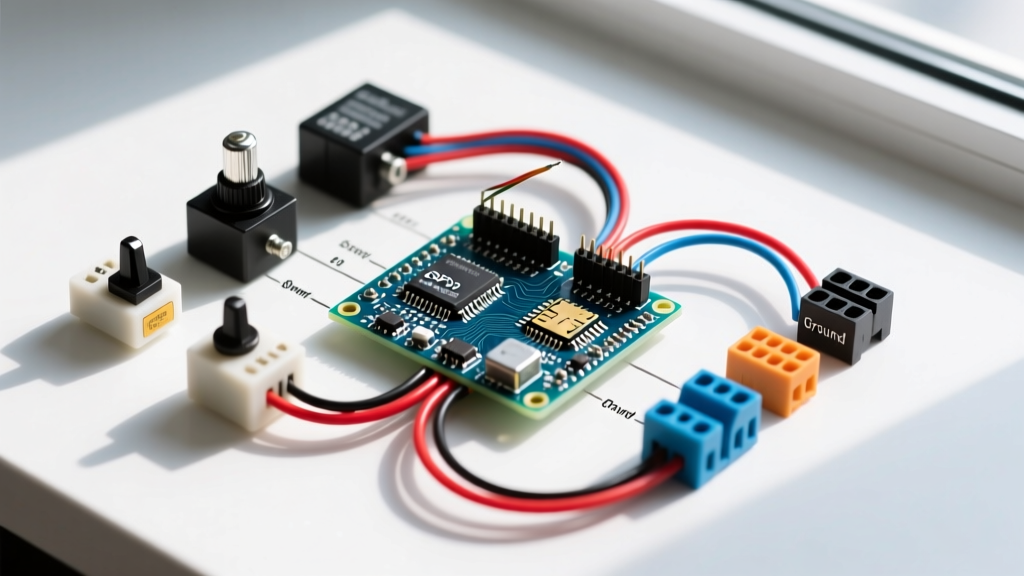

If you are tracing a control panel diagram or designing a motor-reversing circuit, you will inevitably run into a schematic DPDT switch symbol. In the electromechanical world, DPDT (Double Pole, Double Throw) usually refers to an 8-pin relay rather than a manual toggle switch. It gives you two completely isolated circuits (the poles) that can each be thrown between two different paths (the throws).
Whether you are wiring an Omron MY2N or a Schneider Harmony RXM, misunderstanding the schematic symbol or ignoring the contact ratings will result in welded contacts, burnt coils, or a tripped main breaker. Here is your bench-to-jobsite guide to decoding, selecting, and wiring DPDT relays.
Decoding the Schematic DPDT Switch and Relay Symbol
When looking at an IEC or NEMA schematic, the DPDT relay is split into two distinct visual sections: the coil and the contacts. They are galvanically isolated, meaning the control circuit and the load circuit share no direct electrical connection.
- The Coil (Control Side): Usually drawn as a rectangle (IEC) or a circle with diagonal lines (NEMA). It is labeled with a designation like 'K1' or 'CR1'. This is the electromagnet. When you apply the rated voltage here, it generates the magnetic field that pulls the armature.
- The Contacts (Load Side): Drawn as switch blades. In a DPDT configuration, you will see two common (COM) lines, each branching into a Normally Open (NO) and Normally Closed (NC) path. A dashed mechanical linkage line often connects the two switch blades to the coil symbol, indicating they move together.
On a standard 8-pin plug-in DPDT relay, the pinout is almost universally standardized across major manufacturers: Pins 2 and 7 are the coil. Pole 1 uses pins 1 (COM), 4 (NC), and 3 (NO). Pole 2 uses pins 8 (COM), 5 (NC), and 6 (NO). Always verify with the datasheet, but this layout holds true for about 95% of industrial 8-pin relays you will encounter.
Load Selection Decision Path and Rating Table
The most common mistake DIYers and junior techs make is sizing a relay based solely on its maximum resistive amperage. A relay rated for 10A resistive will fail rapidly if you use it to switch a 10A motor. Inductive loads store energy in magnetic fields and release it as an arc when the contacts open.
When asking which rating column governs this load, you must look at the specific breaking capacity or horsepower (HP) rating for inductive/motor loads, not the general AC/DC amperage.
| Load Type | Governing Rating Column | Inrush / Arc Factor | Example Application |
|---|---|---|---|
| Resistive | Max AC/DC Amperage (e.g., 10A @ 250VAC) | 1x (No inrush) | Heaters, incandescent lamps, dummy loads |
| Inductive | Breaking Capacity / cos φ rating (e.g., 5A @ cos φ=0.4) | 3x to 5x inrush; high opening arc | Solenoids, contactor coils, transformers |
| Motor (AC) | HP Rating or FLA/LRA (Locked Rotor Amps) | 6x to 8x inrush (LRA) | Fans, pumps, compressor clutches |
| Lamp (Tungsten) | Tungsten / TV Rating | 10x to 15x cold inrush | Halogen arrays, large incandescent banks |
Wiring the Coil and Contacts (with DC Flyback Protection)
Wiring the contacts is straightforward: line voltage to the Common pins, load to the NO or NC pins depending on your fail-safe logic. The coil side, however, requires specific attention, especially when driven by a DC source like a PLC transistor output or a microcontroller.
- Wire the Load Side First: Connect your load to pins 3 and 6 (NO) or 4 and 5 (NC). Connect your line voltage to pins 1 and 8 (COM). Keep load wiring away from the coil pins to prevent inductive noise coupling.
- Wire the Coil: Apply the control voltage to pins 2 and 7. For AC coils, polarity does not matter. For DC coils, pin 2 is typically positive and pin 7 is negative, though the coil itself will energize either way.
- Install DC Flyback Protection: When you de-energize a DC coil, the collapsing magnetic field induces a massive reverse voltage spike ($V = -L \frac{di}{dt}$) that can easily exceed 100V, frying your PLC output or microcontroller GPIO. You must wire a flyback diode (like a 1N4007) in reverse parallel across pins 2 and 7. Connect the diode's cathode (striped end) to the positive supply (Pin 2) and the anode to the negative (Pin 7).
Note: Never put a flyback diode on an AC coil. It will short the AC waveform and blow your control fuse. For AC coils, use an RC snubber network or a Metal Oxide Varistor (MOV) if arc suppression is needed.
Testing, Troubleshooting, and Replacement
When a circuit fails, you need to know how to test the DPDT relay both dead and live, and when to throw it in the bin.
How to Test It Dead and Live
Dead Testing (Power Off): Pull the relay from its socket. Set your multimeter to resistance (Ohms). Measure across pins 2 and 7. A healthy 12VDC coil will typically read between 100 and 200 ohms; a 120VAC coil might read 3,000 to 5,000 ohms. If it reads infinite (open), the coil is burnt. Next, check continuity between COM and NC (should be < 1 ohm) and COM and NO (should be infinite). Press the armature manually with a small screwdriver; the continuity should swap.
Live Testing (Power On): With the circuit energized, measure the voltage across pins 2 and 7. If you have rated voltage but the relay hasn't pulled in, the coil is internally open or the armature is mechanically jammed. If the relay is pulled in, measure the voltage drop across the closed contacts (e.g., from Pin 1 to Pin 3). A healthy contact will drop less than 50mV under load. If you read 1V or more, the contacts are pitted and carbonized.
When to Repair vs. Replace
In 99% of modern applications, you replace, never repair. If a relay contacts are pitted from AC arcing, the metal has physically vaporized and redistributed. Filing or burnishing AC contacts removes the silver-alloy plating, exposing the base brass, which will weld shut on the very next operation. The only exception is low-voltage (< 24V), low-current signal relays where light oxidation causes high contact resistance; these can sometimes be gently burnished with a specialized contact burnishing tool (never sandpaper, which leaves non-conductive grit).
Frequently Asked Questions
What is the difference between a schematic DPDT switch and a DPDT relay?
A schematic DPDT switch usually refers to a manually operated toggle or rocker switch where human force moves the contacts. A DPDT relay is an electromechanical component where a magnetic coil moves the contacts. In schematics, a manual switch lacks a coil symbol and is drawn simply as a dual-blade switch, whereas a relay includes the coil and the dashed mechanical linkage line.
Can I wire two SPDT relays to act as a schematic DPDT switch?
Yes, electrically you can wire two Single Pole Double Throw (SPDT) relays in parallel to switch two separate poles. However, you must wire their coils in parallel (ensuring the control circuit can handle the combined coil current) or series (ensuring the voltage divides correctly). Mechanically, they will not operate with the exact same millisecond timing, which can cause a brief phase mismatch or arc in sensitive AC loads. For true simultaneous switching, use a single monolithic DPDT relay.
Why is my DPDT relay coil burning out when switching DC loads?
If your coil is burning out, the issue is likely on the contact side, not the coil itself. Switching highly inductive DC loads without an arc suppression circuit (like a freewheeling diode across the load) causes a massive voltage spike when the contacts open. This spike can arc across the opening contacts, generating extreme heat and electromagnetic interference (EMI) that degrades the coil's internal insulation over time, eventually causing a short between the coil windings.
How do I identify the common, NO, and NC pins on an unmarked 8-pin DPDT relay?
If the diagram on the relay case has rubbed off, look at the physical pins on the bottom. The two pins that are angled or offset from the rest are almost always the coil (pins 2 and 7). For the remaining six, use a multimeter in continuity mode. Find the two pairs of pins that have continuity (these are your COM and NC pairs). Then, press the armature in manually. The continuity will break on those pins and make on a new set. The pin that is shared between the 'always connected' and 'connected when pressed' states is your Common. Reference the Omron Relay Basics Guide for visual pinout diagrams.