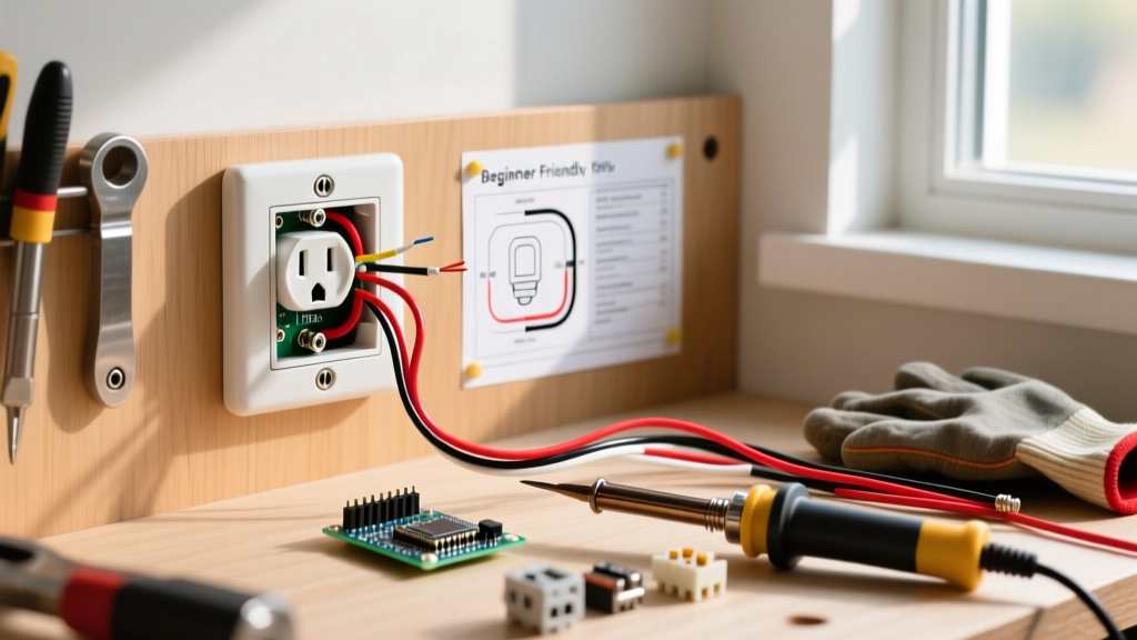
A discolored outlet is a thermal warning sign. The brown or black scorch marks radiating from the plug slots indicate high-resistance heat, almost always caused by failed push-in (backstab) connections or loose terminal screws degrading over time. You must replace the device immediately. Do not attempt to clean it, paint over it, or ignore it; the internal polycarbonate and wire insulation have already suffered thermal damage.
This guide walks you through replacing a standard 15A or 20A duplex receptacle, addressing the root cause of the discoloration, and verifying a safe, code-compliant termination.
Working on branch circuits involves lethal 120V AC mains voltage. Before touching any wires, you must de-energize the circuit at the main breaker panel. Lock out or tag the breaker to prevent accidental re-energizing. Always verify the circuit is dead using a known-working non-contact voltage tester (NCV) and a multimeter before proceeding. Local codes may require a licensed electrician for certain modifications; this guide provides NEC-style guidance, but your local Authority Having Jurisdiction (AHJ) has final authority.
Why Your Outlet is Discolored (The Most Common Botch)
The most common cause of a discolored outlet is the use of backstab (push-in) wire terminations on the back of the receptacle. While the National Electrical Code (NEC) permits push-in connectors for 14 AWG solid copper wire on 15A devices, they are a frequent point of failure in residential wiring.
Inside a backstab connector, a small brass spring grips the wire. Over years of thermal cycling—heating up when you plug in a space heater or vacuum, and cooling down when you unplug it—the spring loses its tension. This creates a micro-gap between the wire and the contact. Electricity jumping across this gap causes micro-arcing. Arcing drastically increases electrical resistance, which generates intense, localized heat. This heat melts the device's plastic faceplate and chars the wire insulation, resulting in the brown discoloration you see.
| Feature | Side-Wiring (Screw Terminals) | Backstabbing (Push-In Connectors) |
|---|---|---|
| Connection Method | Wire wrapped clockwise around screw and torqued down | Wire pushed into a spring-loaded internal hole |
| Thermal Cycling Resilience | Excellent; screw maintains mechanical pressure | Poor; internal spring tension degrades over time |
| Failure Symptom | Rare; loose screws cause arcing but are easily prevented | High resistance, heat, melted faceplate, discolored outlet |
| Wire Gauge Compatibility | Accepts 14 AWG and 12 AWG solid/stranded | Usually restricted to 14 AWG solid only |
Tools and Materials Required
Before opening the electrical box, gather the correct replacement parts and testing equipment. Using the wrong amperage rating or wire gauge is a direct path to a fire.
- Replacement Receptacle: 15A or 20A Tamper-Resistant (TR) duplex receptacle. (NEC Article 406.12 mandates TR receptacles in most residential living spaces to prevent child insertion injuries. Look for brands like Leviton or Eaton).
- Wire Strippers: Precision strippers (e.g., Klein 11055) to avoid nicking the copper conductor.
- Voltage Testers: Non-contact voltage tester (NCV) and a True-RMS digital multimeter (e.g., Fluke 117).
- Screwdrivers: #1 and #2 Phillips, plus a 1/4-inch flathead.
- Lineman Pliers: For cutting damaged wire ends and forming shepherd hooks.
Gauge and Device Rating Rule: You must match the receptacle rating to the circuit breaker and wire gauge. If your breaker is 15A, you must use 14 AWG copper wire (minimum) and a 15A receptacle. If your breaker is 20A, you must use 12 AWG copper wire (minimum) and a 20A receptacle (which features the T-shaped neutral slot). Never install a 20A receptacle on a 14 AWG / 15A circuit, and never put a 15A receptacle on a 20A circuit unless it is part of a multi-receptacle branch circuit as permitted by NEC 210.21(B)(3).
Step-by-Step Discolored Outlet Replacement
Follow these steps precisely, paying close attention to wire colors and termination methods to ensure a low-resistance, fire-safe connection.
- De-energize and Verify: Turn off the branch circuit breaker at the panel. Insert your NCV tester into the top and bottom slots of the discolored outlet. The tester must remain completely silent and unlit. Remove the faceplate and test the exposed screw terminals directly with the NCV to confirm zero voltage.
- Extract the Device: Remove the top and bottom mounting screws securing the receptacle to the drywall box. Gently pull the device out, taking care not to stress the wires. If the plastic is brittle from heat, it may crumble; support it from behind.
- Inspect and Prep the Conductors: Examine the black (hot), white (neutral), and bare copper (ground) wires. If the insulation on the black or white wires is melted, charred, or brittle, you must cut the wire back past the damaged section using your lineman pliers until you reach clean, flexible insulation and bright, unoxidized copper. If you cannot reach undamaged wire, you must splice in a new pigtail using a wire nut.
- Strip the Wires: Use the 14 AWG or 12 AWG hole on your wire strippers to strip exactly 3/4 inch of insulation from the black, white, and bare copper wires. Do not nick the copper; a nicked wire creates a hot spot and a future break point.
- Form Shepherd Hooks: Use the needle-nose pliers or the gripping hole of your wire strippers to bend a tight, clockwise hook at the end of each exposed conductor. The clockwise direction ensures that tightening the screw pulls the hook tighter around the terminal, rather than pushing it out.
- Terminate the Hot Wire: Loop the exposed black (hot) wire clockwise around the brass-colored screw terminal on the new receptacle. Ensure no bare copper extends past the screw head, and no insulation is trapped under the screw washer. Tighten the screw firmly until the hook is fully compressed (approx. 14 in-lbs of torque).
- Terminate the Neutral Wire: Loop the exposed white (neutral) wire clockwise around the silver-colored screw terminal. Tighten firmly. (Note: If you are wiring a 20A circuit and using the back-wire clamp plates instead of side screws, insert the white wire into the back clamp marked 'W' or 'White', and torque the screw to the manufacturer's spec).
- Terminate the Ground Wire: Loop the bare copper (ground) wire clockwise around the green grounding screw at the bottom of the receptacle. If the metal electrical box is also grounded, ensure a separate grounding pigtail connects the box to the device ground or use a self-grounding receptacle if permitted by your local AHJ.
- Dress the Box and Mount: Carefully fold the wires into the back of the box. Push the black and white wires to the back and sides, keeping the bare copper ground wire routed safely away from the hot brass terminals. Mount the receptacle to the box using the provided 6-32 machine screws. Install a new, clean faceplate.
Verify and Test Your Wiring
Do not assume the wiring is correct just because the device is mounted. Before plugging in any appliances, restore power at the breaker panel and verify the voltage and polarity using a digital multimeter set to AC Volts (V~).
| Probe 1 (Red) | Probe 2 (Black) | Expected Reading | What it Verifies |
|---|---|---|---|
| Short Slot (Hot) | Long Slot (Neutral) | 114V - 126V AC | Correct Line-to-Neutral voltage and polarity |
| Short Slot (Hot) | U-Pin (Ground) | 114V - 126V AC | Ground path is continuous back to the panel |
| Long Slot (Neutral) | U-Pin (Ground) | < 2.0V AC (Ideally 0V) | Neutral and Ground are isolated at the receptacle (no bootleg ground) |
If your Line-to-Neutral reading is zero, the breaker is off or a hot wire is disconnected. If your Neutral-to-Ground reading shows 120V, you have reversed the black and white wires at the terminals—de-energize immediately and swap them. According to the Consumer Product Safety Commission (CPSC), improper grounding and reversed polarity are leading contributors to residential electrical shocks and appliance damage.
Frequently Asked Questions
Is a slightly discolored outlet a fire hazard?
Yes. Even slight yellowing or browning around the plug slots indicates that the internal temperature of the receptacle has exceeded the thermal rating of the polycarbonate plastic. The National Fire Protection Association (NFPA) consistently lists electrical distribution and lighting equipment as a top cause of home structure fires. Discoloration means the connection is actively degrading; it is a matter of time before the resistance increases enough to ignite surrounding dust, insulation, or drywall paper.
Why is my outlet discolored but the breaker never tripped?
Circuit breakers are designed to protect the wire inside the walls from drawing more current than its ampacity (e.g., 15 amps for 14 AWG). A loose backstab connection creates a high-resistance series fault. This fault generates intense localized heat at the receptacle while actually reducing the total current flowing through the circuit. Because the total amperage never exceeds the 15A or 20A threshold, the breaker's thermal-magnetic trip mechanism never activates, allowing the outlet to slowly melt without tripping the panel.
Can I just clean a discolored outlet instead of replacing it?
No. The discoloration is not surface dirt; it is a chemical change in the plastic caused by thermal degradation. The internal brass contacts have also likely lost their spring tension and suffered oxidation, which permanently increases their electrical resistance. Cleaning the faceplate with bleach or solvent will only mask the visual warning sign while leaving the fire hazard fully intact. The device must be physically removed and replaced.
What if the wire insulation inside the box is also melted?
If the black or white wire insulation is melted, brittle, or flaking off inside the electrical box, you cannot simply attach it to a new receptacle. Exposed or compromised insulation inside a crowded box can lead to a short circuit or ground fault. You must use your lineman pliers to cut the wire back until you reach clean, intact insulation. If cutting the wire back leaves it too short to reach the terminal, you must strip a new 6-inch piece of matching gauge wire (14 AWG or 12 AWG), splice it to the existing wire using a UL-listed wire nut or WAGO lever connector, and use the new pigtail to terminate at the receptacle.