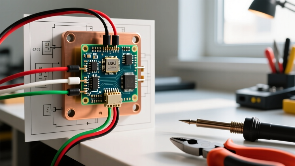
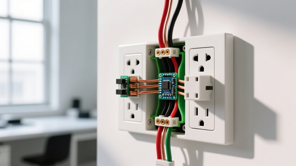
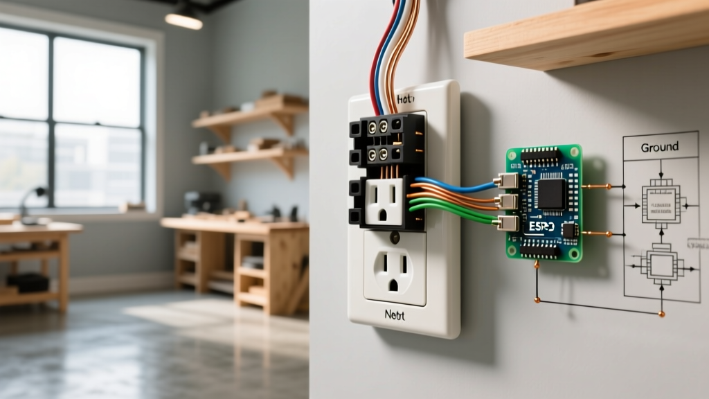
Using a PNP as switch is the standard method for high-side DC switching in low-voltage control circuits, smart home panels, and microcontroller-driven automation. Unlike an NPN transistor that switches the ground path, a PNP bipolar junction transistor (BJT) interrupts the positive voltage supply. When you apply a voltage lower than the emitter to the base, the transistor saturates, allowing current to flow from the emitter to the collector and energizing your load.
While solid-state PNP switches like the TIP32 or 2N2907 offer silent, bounce-free operation, they are frequently paired with—or used to replace—electromechanical relays. To design a reliable circuit, you must understand how solid-state semiconductor ratings map to traditional electromechanical specifications, how to protect the junction from inductive kickback, and how to verify the component on the bench.
PNP vs Electromechanical Relay: Rating Table and Governing Columns
When deciding between a solid-state PNP switch and an electromechanical relay, you are comparing semiconductor physics to moving magnetic contacts. Below is a direct comparison between a common power PNP transistor (TIP32) and a standard 12V DC relay (Omron G2R-1-E).
| Parameter | TIP32 (PNP Transistor) | Omron G2R-1-E (Relay) |
|---|---|---|
| Control Metric | Base Current (Ib) & Vbe | Coil Voltage (12V DC) & Coil Resistance |
| Load Metric | Continuous Collector Current (Ic) = 3A | Contact Rating = 16A @ 250V AC |
| Max Voltage | Collector-Emitter Voltage (Vceo) = 100V | Max Switching Voltage = 440V AC |
| Breaking Capacity | Not applicable (requires external fuse) | Breaking Capacity = 16A resistive |
| On-State Loss | Vce(sat) ≈ 1.2V (dissipates heat) | Contact Resistance ≈ 30mΩ (negligible) |
Which Rating Column Governs This Load?
For a PNP transistor, the Continuous Collector Current (Ic) and Collector-Emitter Voltage (Vceo) govern the load. You must derate the Ic based on ambient temperature; a TIP32 rated for 3A at 25°C will safely handle only about 1.5A at 100°C without a heatsink. For an electromechanical relay, the contact rating and breaking capacity govern the load. Breaking capacity is critical for inductive loads, as the physical air gap must extinguish the arc when the contacts open. A PNP transistor does not arc, but it will avalanche and short out if the load's flyback voltage exceeds its Vceo rating.
Wiring Explained: Control Side vs Load Side (Coil vs Contact)
Understanding the wiring topology requires mapping the solid-state terminals to their electromechanical equivalents.
- The Control Side (Base vs Coil): In a relay, you wire the coil between a control voltage and ground. In a PNP circuit, the control side is the Base. Because a PNP is a current-controlled device, you never wire a microcontroller GPIO directly to the base. You must use a base resistor ($R_b$) to limit current. To turn the PNP on, the GPIO must pull the base voltage at least 0.7V lower than the emitter voltage. To turn it off, the GPIO must pull the base voltage up to the emitter voltage (or use a pull-up resistor to prevent floating).
- The Load Side (Collector/Emitter vs Contact): In a relay, the contacts (Common, NO, NC) switch the load. In a PNP circuit, the Emitter connects to the positive supply (Vcc), and the Collector connects to the positive terminal of the load. The load's negative terminal returns to ground. This is known as high-side switching.
If your PNP transistor is switching an inductive load—such as a relay coil, a solenoid, or a DC motor—you must wire a flyback diode (e.g., 1N4007) in reverse bias across the load. Wire the cathode (stripe) to the positive side (Collector) and the anode to the negative side. When the PNP turns off, the collapsing magnetic field generates a massive reverse voltage spike. Without the diode, this spike will instantly exceed the PNP's Vceo rating, punching through the silicon junction and permanently shorting the transistor.
Selection Decision Path by Load Type
Not every load should be switched by a PNP BJT. Use this decision tree to select the right switching component based on your specific load characteristics.
| Load Type | Characteristics | Best Switch Choice | Why? |
|---|---|---|---|
| Resistive (Heaters, LEDs, small relays) | Steady current, no inrush, no arcing. | PNP BJT or Logic-Level MOSFET | BJTs are cheap and easy to drive for loads under 2A. For higher currents, use a P-channel MOSFET to avoid base current losses. |
| Inductive (Solenoids, contactor coils) | High inrush, massive flyback spike on turn-off. | PNP BJT + Flyback Diode OR Relay | A PNP works well if properly snubbed with a diode. If the inductive kick is too large for the silicon die, use the PNP to drive a mechanical relay instead. |
| Motor (DC brushed, steppers) | High starting stall current, EMI noise, frequent switching. | Electromechanical Relay or H-Bridge IC | Motors generate severe EMI and stall currents 5x-10x the running current. A discrete PNP will likely overheat or suffer thermal runaway without massive heatsinking. |
| AC Mains (120V/240V AC appliances) | High voltage, alternating polarity. | Electromechanical Relay or TRIAC | Never use a standard PNP BJT for AC. It will conduct on one half-cycle and avalanche on the reverse half-cycle. Use a relay or an opto-isolated TRIAC. |
Testing Dead and Live: Diode Checks and Saturation Voltage
When a circuit fails, you need to know if the PNP transistor is the culprit. Here is how to test it on the bench and in-circuit.
How to Test It Dead (Out of Circuit)
Set your multimeter to Diode Test mode. A PNP transistor is essentially two diodes sharing a common cathode (the Base).
- Place the red probe on the Base and the black probe on the Emitter. You should read a forward voltage drop of 0.5V to 0.8V.
- Keep the red probe on the Base and move the black probe to the Collector. You should read a similar 0.5V to 0.8V drop.
- Reverse the probes (black on Base, red on Emitter/Collector). The meter should read 'OL' (Open Loop).
- Test between Collector and Emitter in both directions. It should read 'OL'. If it reads near 0.00V, the junction has shorted and the part is dead.
How to Test It Live (In Circuit)
Power the circuit and command the switch to turn ON. Measure the voltage between the Collector and the Emitter ($V_{ce}$). A properly saturated PNP switch will show a very low voltage drop, typically 0.2V to 1.2V depending on the part and load current. If you measure the full supply voltage (e.g., 12V) across the Collector and Emitter while the base is being pulled low, the transistor is either not receiving base current, or the internal bond wire has blown open.
When to Repair vs Replace
Always replace a PNP transistor. Unlike industrial contactors where you can file down pitted contacts or swap out a burnt coil, a TO-220 or TO-92 transistor is a monolithic silicon die encased in epoxy. If it fails, the internal crystalline structure is compromised. Desolder it, clean the pads with flux and wick, and solder in a new component. If the replacement blows immediately upon power-up, your load is shorted or you forgot the flyback diode.
Frequently Asked Questions
Can I use a PNP as switch for high-side AC mains loads?
No. A standard PNP bipolar junction transistor is a unipolar DC device. If you connect it to 120V AC, it will conduct during the positive half-cycle and experience reverse-bias avalanche breakdown during the negative half-cycle, destroying the silicon. For switching AC mains loads from a low-voltage DC microcontroller, use an electromechanical relay or a solid-state relay (SSR) featuring an internal opto-isolated TRIAC.
Why does my PNP transistor get hot when switching a 12V relay coil?
Heat in a BJT is caused by the saturation voltage drop ($V_{ce(sat)}$) multiplied by the load current. If your 12V relay coil draws 150mA, and your PNP has a $V_{ce(sat)}$ of 1.0V, the transistor dissipates 150mW of heat. While 150mW won't melt a TO-220 package, if you are driving a heavier load like a 1A solenoid, that 1V drop turns into 1 full Watt of heat, requiring a heatsink. To reduce heat, ensure you are supplying enough base current to drive the transistor into deep saturation, or switch to a P-channel MOSFET which has an $R_{ds(on)}$ in the milliohm range.
Do I need a base resistor when driving a PNP as switch from an ESP32?
Yes, absolutely. The Base-Emitter junction of a PNP transistor behaves exactly like a standard silicon diode. If you connect an ESP32 GPIO pin directly to the base of a PNP whose emitter is tied to 12V, the 8.7V differential will force massive current through the GPIO pin, instantly frying the ESP32's internal silicon. You must use a base resistor to limit the current. Furthermore, because the ESP32 outputs 3.3V logic, it cannot fully turn off a PNP connected to a 12V emitter (12V - 3.3V = 8.7V, which still forward-biases the base). You must use an intermediate NPN transistor or an N-channel MOSFET to level-shift the ESP32's 3.3V signal to safely control the high-side PNP.