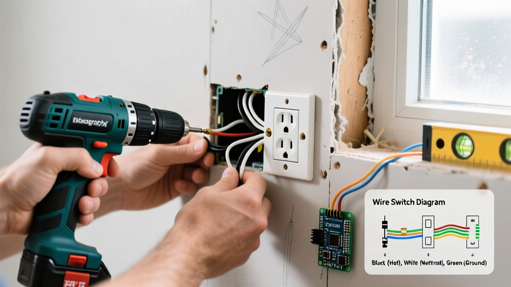

When sizing conductors for a branch circuit or feeder, the direct answer lies in matching your breaker's maximum continuous load to the ampacity values in the 75°C column of NEC Table 310.16 for most modern residential and commercial terminations. Sizing wire isn't just about preventing a fire; it's about ensuring the conductor can handle the thermal stress at the exact point where it connects to your breaker or receptacle.
To read the master table below, locate your target amperage and trace it to the corresponding American Wire Gauge (AWG) or circular mil (kcmil) size. The table is divided by conductor material (Copper vs. Aluminum) and insulation temperature ratings (60°C, 75°C, and 90°C). Bookmark these quick-jump common residential sizes:
- 15A Circuit: 14 AWG Copper (60°C column)
- 20A Circuit: 12 AWG Copper (60°C column)
- 30A Circuit: 10 AWG Copper (60°C column)
- 40A Circuit: 8 AWG Copper (75°C column)
- 50A Circuit: 6 AWG Copper (75°C column)
- 100A Feeder: 3 AWG Copper or 1 AWG Aluminum (75°C column)
- 200A Service: 2/0 AWG Copper or 4/0 AWG Aluminum (75°C column)
The Master NEC 310.16 Ampacity Chart
The following data is sourced directly from the NFPA 70: National Electrical Code (NEC) Table 310.16. These values assume an ambient temperature of 30°C (86°F) and not more than three current-carrying conductors in a raceway or cable.
| AWG / kcmil | Copper 60°C (140°F) | Copper 75°C (167°F) | Copper 90°C (194°F) | Aluminum 75°C (167°F) | Aluminum 90°C (194°F) |
|---|---|---|---|---|---|
| 14 | 15A | 20A | 25A | - | - |
| 12 | 20A | 25A | 30A | 15A | 20A |
| 10 | 30A | 35A | 40A | 25A | 30A |
| 8 | 40A | 50A | 55A | 35A | 45A |
| 6 | 55A | 65A | 75A | 45A | 55A |
| 4 | 70A | 85A | 95A | 60A | 75A |
| 3 | 85A | 100A | 115A | 75A | 85A |
| 2 | 95A | 115A | 130A | 90A | 100A |
| 1 | 110A | 130A | 145A | 100A | 115A |
| 1/0 | 125A | 150A | 170A | 120A | 135A |
| 2/0 | 145A | 175A | 195A | 135A | 150A |
| 3/0 | 165A | 200A | 225A | 155A | 170A |
| 4/0 | 195A | 230A | 260A | 180A | 205A |
Which Temperature Column Applies to Your Installation?
The most common mistake DIYers make is looking at the 90°C column because they bought THHN wire, which is rated for 90°C. However, the NEC enforces a strict 'weakest link' rule under Article 110.14(C). You must size your wire based on the lowest temperature rating of any connected device, terminal, or conductor in the circuit.
Almost all modern residential breakers, receptacles, and switches are rated for 75°C terminations. Therefore, even if your wire insulation can handle 90°C, the termination point cannot. You must use the 75°C column to determine your base ampacity for circuits over 100A, and the 60°C column for circuits rated 100A or less (unless the equipment is specifically marked otherwise).
The NM-B (Romex) Exception: If you are using standard nonmetallic-sheathed cable (NM-B, commonly known by the brand name Romex), NEC Article 334.80 explicitly mandates that you use the 60°C ampacity column, regardless of the fact that the individual conductors inside the jacket are technically rated for 90°C. For example, 6 AWG NM-B is strictly limited to 55A, not the 75A you might mistakenly pull from the 90°C copper column.
Derating Factors: When the Base Chart Fails
The ampacities listed in the table above assume ideal conditions: an ambient temperature of 30°C (86°F) and a maximum of three current-carrying conductors bundled together. When real-world jobsite conditions deviate from this, you must apply derating factors that modify the base value.
1. Bundling (More than 3 Current-Carrying Conductors): When you pull multiple circuits through a single conduit, the heat generated by adjacent wires cannot dissipate. According to NEC 310.15(C)(1), if you have 4 to 6 current-carrying conductors in a raceway, you must multiply the base ampacity by 80%. For 7 to 9 conductors, the factor drops to 70%.
Worked Example: You are pulling four 8 AWG THHN conductors (two hots, one neutral, one ground) through a single EMT conduit to feed a multi-wire branch circuit. The ground does not count as a current-carrying conductor. You have 3 current-carrying conductors. No derating is required. However, if you add a second circuit (adding two more hots and a shared neutral), you now have 5 current-carrying conductors. You must use the 90°C column for derating calculations: 8 AWG THHN at 90°C is 55A. Multiply 55A by 0.80 (the 80% adjustment factor) = 44A. Because 44A is greater than your 40A load, the 8 AWG wire is still legally compliant, but you are now operating on a tight margin.
2. Ambient Temperature Corrections: If your conduit runs through an attic in the middle of summer where temperatures reach 120°F (49°C), you must consult the temperature correction factors in NEC Table 310.15(B)(1). At 120°F, a 90°C rated wire must be derated to 82% of its base ampacity. Always check the Southwire Wire & Cable Resources guides for specific jacket limitations in high-heat environments.
What This Amp Chart Cannot Tell You
While NEC Table 310.16 is the bible for thermal ampacity, it is not a comprehensive wire sizing tool. Relying solely on this chart will leave you blind to three critical failure modes:
- Voltage Drop: The NEC amp chart does not account for distance. If you are running a 50A circuit to a detached garage 150 feet away, 6 AWG copper will safely carry the current without melting, but the voltage drop will exceed the recommended 3% threshold for branch circuits. You will need to upsize to 4 AWG or 3 AWG purely to maintain voltage stability at the load, a calculation governed by physics (Ohm's Law) rather than NEC minimums.
- Conduit Fill Capacity: The chart tells you the wire size, but not if it will physically fit in your pipe. NEC Chapter 9, Table 1 limits conduit fill to 40% for three or more wires. If you try to pull four 2 AWG THHN wires through a 3/4-inch EMT conduit, they will physically jam, regardless of what the ampacity chart says.
- Short-Circuit Interrupting Capacity: Ampacity measures sustained thermal load. It does not tell you how the wire will react to a 10,000-amp short circuit fault. That is determined by the breaker's AIC (Ampere Interrupting Capacity) rating and the wire's mechanical bracing, not its continuous ampacity.
Disclaimer: The data provided here reflects NEC-style guidance for educational and planning purposes. Your local Authority Having Jurisdiction (AHJ) or electrical inspector always has final authority on code compliance and may enforce local amendments that supersede baseline national standards.