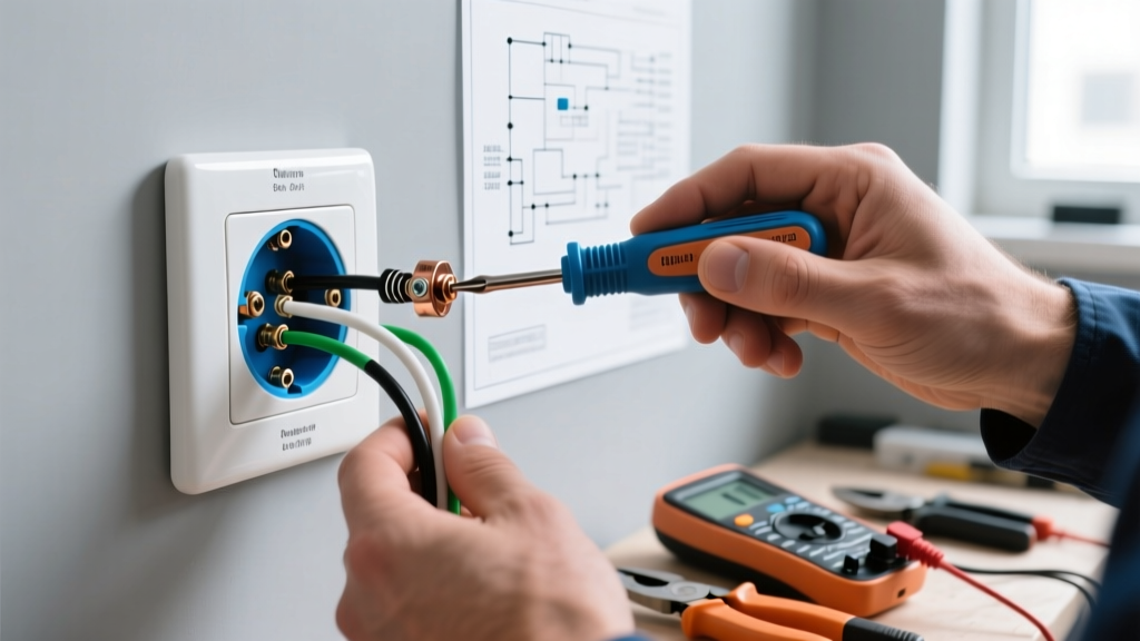
Electrical wiring for outlets is the branch circuit design and conductor sizing process that delivers safe, code-compliant power to receptacles based on anticipated load and continuous duty rules. Getting this right dictates your wire gauge, overcurrent protection size, and the physical configuration of the receptacles, directly determining whether your circuit will safely handle a heavy load or trip the moment you turn on a vacuum. The most frequent mistake DIYers make is confusing a receptacle’s physical amperage rating (the shape of the slots) with the branch circuit’s breaker rating, leading to the false assumption that a 15A duplex outlet cannot legally be installed on a 20A breaker circuit.
The Core Sizing Matrix: Breakers, Wire, and Receptacles
When planning electrical wiring for outlets, you must match three components: the overcurrent protective device (breaker), the conductor ampacity (wire), and the receptacle configuration. The National Electrical Code (NEC) strictly governs how these interact to prevent conductor overheating and fire. Below is the foundational sizing matrix for standard 120V residential branch circuits, based on the 60°C ampacity column of NEC 310.16 (which applies to standard NM-B Romex cable).
| Breaker Size | Min Copper Wire (NM-B) | Max Receptacle Rating Allowed | Typical Use Case |
|---|---|---|---|
| 15 Amp | 14 AWG | 15A only | General living spaces, bedrooms, hallways |
| 20 Amp | 12 AWG | 15A or 20A | Kitchens, bathrooms, garages, outdoors |
| 30 Amp | 10 AWG | 30A (Specialty) | RV outlets, heavy-duty dryer/welder plugs |
| 50 Amp | 6 AWG | 50A (Specialty) | Electric ranges, large workshop equipment |
Worked Example: The 15-Amp Bedroom Space Heater Trap
To understand what electrical wiring for outlet sizing actually changes in a real circuit, let us run the math on a classic winter failure mode: plugging a 1500W space heater into a standard 15A bedroom outlet.
Heater Wattage: 1500W
Calculated Current (I = P/V): 1500W / 120V = 12.5 Amps
At first glance, a 12.5A draw seems perfectly safe on a 15A breaker (12.5A < 15A). However, the NEC defines a continuous load as any load where the maximum current is expected to continue for 3 hours or more. If you run that space heater on a cold night while sleeping, it easily crosses the 3-hour threshold.
For continuous loads, NEC 210.20(A) requires the branch circuit to be rated at 125% of the continuous load.
The Math: 12.5A × 1.25 = 15.625 Amps.
Because 15.625A exceeds the 15A breaker rating, the breaker's thermal bimetallic strip will eventually heat up and trip the circuit after 45 to 90 minutes of continuous use. Furthermore, the 14 AWG wire is only rated for 15A and would be operating outside its safe continuous thermal limits.
The Fix: Either upgrade the electrical wiring for the outlet to a 20A circuit (using 12 AWG wire and a 20A breaker, yielding a 24A continuous capacity), or switch to a lower-wattage heater (e.g., a 1000W model drawing 8.3A, which requires only 10.4A of continuous circuit capacity).
Where You Meet This in Practice: Real-World Installation Rules
Theory only gets you to the hardware store; execution determines if the installation passes inspection and survives a decade of use. When you are physically pulling wire and terminating outlets, three practical rules dominate the jobsite.
1. The 60°C vs. 75°C Ampacity Column Reality
Modern THHN wire in conduit is rated for 90°C, and most modern 20A breakers and receptacles have 75°C rated terminals. However, if you are using standard NM-B (Romex) cable, NEC 334.80 explicitly limits its ampacity to the 60°C column of Table 310.16, regardless of the terminal ratings. This means 12 AWG NM-B is strictly capped at 20A. You cannot use the 75°C column to uprate NM-B to 25A just because your receptacle terminals are stamped '75°C'.
2. Torque Specifications are Now Law
Loose terminal screws cause arcing, which causes fires. Since the 2017 NEC update (and reinforced in 2020/2023 via NEC 110.14(D)), you must tighten terminal screws to the manufacturer's specified torque. For standard 15A and 20A Leviton or Hubbell duplex receptacles, this is typically 14 in-lbs. Use an insulated torque screwdriver (like the Klein Tools 60204) rather than guessing by feel. Hand-tightening often results in 8 to 10 in-lbs, which is insufficient for 12 AWG solid copper wire under heavy load.
3. Pigtailing vs. Feed-Through
When wiring multiple outlets on a single branch circuit, do not rely on the receptacle's internal brass tabs to carry the full circuit current to the next downstream device (feed-through). If the receptacle fails or is removed, the downstream devices lose their neutral or hot path, and the internal tabs can overheat if the downstream load is high. Always use a wire nut or WAGO 221 lever connector to pigtail the incoming hot, outgoing hot, and receptacle hot together. This ensures the receptacle only carries its own localized load.
Common Wiring Confusions and Code Caveats
Even experienced hobbyists trip over specific edge cases in outlet wiring. Here is a breakdown of the most common points of confusion.
Can I use the push-in 'backstab' connectors on the back of the outlet?
Technically yes for 14 AWG solid wire on 15A circuits, but practically, you should avoid them. Push-in spring connectors have a smaller contact surface area than wrapping the wire around the terminal screw. Under heavy continuous loads, the spring tension can relax over time due to thermal cycling, leading to high resistance and melted plastic. Always use the side terminal screws or the screw-clamp plates found on higher-grade 'spec' receptacles.
What is a Multi-Wire Branch Circuit (MWBC) and why does it matter for outlets?
An MWBC shares a single neutral wire between two hot legs (L1 and L2) on a 240V split-phase system, effectively giving you two 120V circuits in one cable (e.g., 14/3 or 12/3 NM-B). If you are wiring kitchen outlets on an MWBC, NEC 210.4 requires a simultaneous disconnect. This means you must use a 2-pole breaker or install an approved handle-tie on two adjacent single-pole breakers. If you turn off only one breaker to replace an outlet, the shared neutral will still be carrying the return current from the other active leg, presenting a lethal shock hazard.
Do I need a GFCI or AFCI for standard bedroom outlets?
Modern code requires both, but they serve different purposes. AFCI (Arc-Fault Circuit Interrupter) protection is required for almost all 120V, 15A and 20A bedroom and living space outlets to prevent fires from sparking wires inside walls. GFCI (Ground-Fault Circuit Interrupter) is required where water is present (kitchens, bathrooms, garages, outdoors) to prevent electrocution. You can achieve bedroom AFCI protection by installing an AFCI breaker in the main panel, allowing you to use standard, non-AFCI receptacles on the wall.