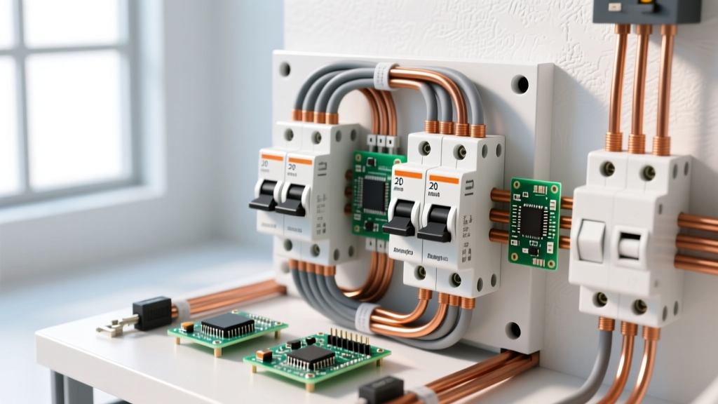
A contactor switch diagram maps two entirely isolated circuits: the low-power control circuit (the coil) and the high-power load circuit (the main contacts). For a standard 3-phase motor application, you need an IEC AC-3 rated contactor with a coil voltage matching your control logic (e.g., 24VDC or 120VAC) and a contact ampacity exceeding the motor’s Full Load Amps (FLA) by at least 115%. If you are switching resistive heating elements, you must instead look at the AC-1 rating column, which governs non-inductive loads.
Misreading the switch diagram or confusing the coil voltage with the contact voltage rating is the most common cause of premature contactor failure. This guide breaks down the schematic symbols, utilization categories, and exact testing procedures you need to specify, wire, and troubleshoot electromechanical contactors with confidence.
Decoding the Contactor Switch Diagram: Coil vs. Contacts
Every contactor switch diagram divides the component into two functional halves. Understanding this isolation is critical for safe wiring and proper troubleshooting.
The Coil Side (Control Circuit)
On the schematic, the coil is represented by a circle or rectangle, typically labeled A1 and A2. This is the electromagnet that pulls the contacts closed. The voltage applied here (e.g., 24VAC, 120VAC, 24VDC) is entirely independent of the load voltage. You can safely use a 24VDC coil to switch a 480VAC 3-phase motor, provided the control circuit is properly isolated via a step-down transformer or DC power supply.
The Contact Side (Load Circuit)
The main power contacts are labeled L1, L2, L3 (line in) and T1, T2, T3 (load out). Auxiliary contacts, used for logic feedback or holding circuits, are marked with two-digit numbers (e.g., 13/14 for Normally Open, 21/22 for Normally Closed). The auxiliary circuit carries minimal current (usually under 10A) and is used to signal a PLC or illuminate a pilot light.
The Rating Table: Which Column Governs Your Load?
Contactors are not rated by a single amperage number. The IEC 60947-4-1 standard defines "utilization categories" that dictate how much current the contacts can safely make and break. According to IEC standards, applying an AC-1 rated contactor to a motor load will result in welded contacts and catastrophic failure.
| Utilization Category | Typical Load Type | Governing Rating Column | Making/Breaking Capacity |
|---|---|---|---|
| AC-1 | Non-inductive / Resistive (Heaters) | Thermal Current (Ith) | 1.0x Rated Current |
| AC-3 | Squirrel-Cage Motors (Starting/Running) | Operational Current (Ie) | Make: 10x Ie / Break: 8x Ie |
| AC-4 | Motors (Plugging, Jogging, Reversing) | Operational Current (Ie) | Make: 12x Ie / Break: 10x Ie |
Which column governs? If you are switching a motor, the AC-3 Operational Current (Ie) column is your governing metric, not the maximum thermal current (Ith). A contactor might boast a 32A thermal rating (AC-1), but only be rated for 18A at 400VAC under AC-3 motor starting conditions.
Load Selection Decision Path: From Application to Part Number
Use this decision tree to select the correct contactor based on your specific load profile. Do not default to a generic "30A contactor" without checking the utilization category.
| IF your load is... | AND the operating duty is... | THEN select Utilization Category... | Concrete Part Pick (Example) |
|---|---|---|---|
| Resistive Heating Elements | Continuous ON/OFF | AC-1 (Size to Ith) | Eaton C30CN (30A AC-1) |
| HVAC Compressor / Fan Motor | Standard Start & Run | AC-3 (Size to Motor FLA) | Schneider TeSys D LC1D18 (18A AC-3) |
| Hoist or Crane Motor | Frequent Jogging / Plugging | AC-4 (Derate heavily) | Schneider TeSys F LC1F115 |
Default Recommendation: For 90% of DIY and light-commercial 3-phase motor applications (up to 10 HP at 230V), the Schneider Electric TeSys D LC1D18 (or the equivalent Eaton XTCE018) with a 120VAC coil is the definitive choice. It provides 18A AC-3 rating, integrated auxiliary contacts (1 NO), and accepts standard ring-tongue or ferrule terminations.
Field Testing: How to Verify Dead and Live
When a motor fails to start or a contactor hums loudly, you need a systematic approach to isolate the fault. Always follow NFPA 70E guidelines and verify zero energy before touching terminals.
Dead Testing (Power Off & Locked Out)
- Coil Resistance: Set your multimeter to Ohms (Ω). Measure across A1 and A2. A healthy 120VAC coil typically reads between 15Ω and 40Ω. A reading of OL (infinite) means an open coil (burned out). A reading near 0.5Ω indicates a shorted coil.
- Contact Continuity: With the contactor manually depressed (using the built-in test button on the armature), measure across L1-T1, L2-T2, and L3-T3. You should read < 0.5Ω. If you read > 2Ω, the contacts are pitted or carbon-fouled and the contactor must be replaced.
- Ground Fault Check: Measure from each load terminal (T1, T2, T3) to the contactor's metal mounting plate or ground lug. It must read OL. Any continuity means internal insulation breakdown.
Live Testing (Energized & Under Load)
Warning: Only perform live testing if you are qualified and wearing appropriate PPE.
- Coil Voltage: With the start command active, measure AC/DC voltage across A1 and A2. It must be within 85% to 110% of the coil's nominal rating. A 120VAC coil dropping to 90V will chatter and burn out the coil due to insufficient magnetic pull.
- Voltage Drop Across Contacts: With the motor running, measure the AC voltage from L1 to T1, L2 to T2, etc. A healthy closed contact will drop less than 0.2V. If you measure 2V to 5V across a single pole under load, that contact is generating massive heat (I²R losses) and is nearing failure.
Repair vs. Replace: Diagnosing Contactor Failure
Contactors are generally considered disposable components in modern industrial panels, but knowing when to repair versus replace saves downtime and money.
When to Replace the Contactor
- Severe Contact Pitting: If the silver-alloy contact pads are deeply cratered or show signs of arc melting, replace the unit. Never file or sand contact pads. Sanding removes the silver-alloy surfacing, exposing the base copper, which will oxidize rapidly and cause a high-resistance hot spot.
- Cracked Arc Chutes: The plastic arc chutes (the covers over the main contacts) quench the electrical arc when the contacts open. If they are cracked, melted, or missing, the arc will sustain, potentially causing a phase-to-phase flashover.
- Coil Burnout: If the coil reads open, or the plastic bobbin is melted/discolored, the entire contactor must be swapped. Replacing just the coil is rarely cost-effective for frames under 40A.
When to Repair or Maintain
- Loose Terminal Lugs: Thermal cycling loosens screw terminals. If the wire insulation is intact but the terminal is hot, torque the lugs to the manufacturer's spec (typically 1.2 to 2.5 Nm for frame-size D contactors) using a calibrated torque screwdriver.
- Failed Auxiliary Contacts: If the main power contacts are healthy but the 13/14 feedback circuit is dead, you can often unclip and replace the front-mounted auxiliary contact block without removing the main contactor from the DIN rail.
- Dust and Debris: In woodworking or agricultural environments, conductive dust can cause coil shorts or contact tracking. Use low-pressure dry compressed air to blow out the armature gap and arc chutes during annual maintenance.
By strictly following the switch diagram, matching the IEC utilization category to your specific load, and verifying voltage drop under live conditions, you ensure your motor starters and heating circuits operate reliably for years. For general-purpose motor switching up to 10 HP, standardizing your panel inventory on the Schneider TeSys D series (LC1D) with AC-3 ratings provides the best balance of global availability, proven arc-quenching performance, and straightforward wiring.