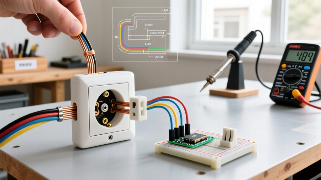
In electrical schematics and wiring diagrams, 'circuit symbols wire' refers to the specific line styles, junction dots, and sheathing notations used to represent conductor types and their physical routing. Unlike simple solid lines that merely denote basic electrical continuity, specialized wire symbols tell you how the wire is physically constructed, shielded, and installed in the field. Below is the master reference table for these symbols, followed by regional color code mappings and bench-tested troubleshooting protocols for degraded print and faded insulation.
Master Reference Table for Circuit Wire Symbols
When reading a schematic, the base line represents the copper or aluminum conductor itself. Modifications to that line—such as dashes, hatching, or intersecting geometric shapes—indicate the physical jacketing, shielding, or routing method. Use this table to decode the physical wire equivalent from the paper symbol.
| Symbol Description | Schematic Representation | Physical Wire Equivalent | Typical Application |
|---|---|---|---|
| Basic Wire / Conductor | Solid straight line | THHN / Solid Copper (e.g., Southwire 12 AWG) | Branch circuits, panel jumpers, basic hookups |
| Shielded Wire | Solid line with dashed outer line or hatch marks | Foil/Braid Shielded Cable (e.g., Belden 8723) | Audio runs, low-voltage sensor lines, VFD motor leads |
| Twisted Pair | Two intertwining sine waves or crossed lines | Cat5e/6, RS-485 cable, DMX cable | Data lines, differential signaling, industrial comms |
| Underground / Direct Burial | Solid line with hash marks underneath | UF-B or USE-2 cable | Landscape lighting, well pumps, solar array trenching |
| Coaxial Cable | Solid line intersecting a circle or parallel lines | RG-6, RG-59, LMR-400 | CCTV, RF antenna feeds, broadband internet |
| Wire Junction (Splice) | Solid dot at line intersection | Wire nut / Wago 221 lever connector | Branch circuit splices, pigtail connections in J-boxes |
| Crossing Wires (No Connection) | Lines crossing with NO dot or a 'jump' arc | Insulated crossover in panel or conduit | Keeping line voltage and low-voltage separated |
How to read the schematic column: If a symbol features a dashed line parallel to the main conductor, it almost always denotes an electrostatic shield (drain wire). If the symbol features a physical box drawn around multiple lines, it denotes a multi-conductor jacket (like NM-B Romex) rather than individual shielded conductors.
Regional Standard Variants: NEC, IEC, and Legacy UK
While organizations like IEEE (Standard 315) and IEC (Standard 60617) do an excellent job standardizing the symbols drawn on paper globally, the physical color codes applied to those wires change drastically depending on your region's governing electrical code. Misapplying a European color code to a North American panel is a fast track to a dead short or a shock hazard.
Below is the translation matrix for the three major wiring standards you will encounter in the wild. For authoritative code references, consult the NFPA National Electrical Code (NEC) for North America, or the All About Circuits wiring reference for international comparisons.
| Function | US / Canada (NEC) | EU / Modern UK (IEC 60446 / BS 7671) | Legacy UK (Pre-2006) |
|---|---|---|---|
| Line / Phase 1 | Black | Brown | Red |
| Line / Phase 2 (240V/3-Phase) | Red / Black | Black / Brown | Yellow / Red |
| Neutral | White or Grey | Blue | Black |
| Earth Ground | Bare Copper or Green | Green with Yellow Stripe | Green with Yellow Stripe |
Common Misreads and the Faded-Marking Safety Protocol
Even with a perfect schematic in hand, field conditions and degraded materials cause errors. Here are the specific rows and symbols people get wrong most often, followed by the protocol for when physical wire markings fail.
The 'Rows People Get Wrong' Notes
- Junction Dot vs. Crossing: A missing dot at an intersection means wires cross but do not connect. Novices often assume a physical crossover on a diagram implies a splice. If there is no solid dot (or a 'hop' arc), the wires are electrically isolated from one another.
- Shield vs. Conduit: A dashed line wrapped around a wire means shielded cable (like a foil-wrapped sensor wire). It does not mean wires pulled inside a metal conduit (EMT). Conduit is drawn as a physical boundary box or a specific enclosure symbol encompassing the lines.
- Earth Ground vs. Neutral Bus: The earth ground symbol (three descending horizontal lines) is frequently confused with the neutral bus symbol (a single solid line with smaller tick marks) in older, hand-drawn schematics. Remember: neutral carries return current; earth ground carries current only during a fault.
Safe Interpretation When Markings are Faded or Missing
Wire insulation print (e.g., '12 AWG THHN 600V') fades over time due to UV exposure in outdoor enclosures, heat degradation in attics, or chemical off-gassing in industrial panels. When you cannot read the AWG or voltage rating printed on the jacket, you must verify the conductor physically before sizing your breaker.
The Faded-Marking Verification Protocol:
- De-energize and Verify: Kill the breaker and test for zero voltage line-to-neutral and line-to-ground.
- Strip and Measure: Strip a 1/2-inch section of insulation. Use a digital micrometer caliper (like a Mitutoyo 500-196-30) to measure the bare copper diameter. Do not use a ruler; the tolerance is too tight.
- Match to AWG Table:
- 10 AWG = 0.1019 inches (2.588 mm)
- 12 AWG = 0.0808 inches (2.052 mm)
- 14 AWG = 0.0641 inches (1.628 mm)
- Check Stranding: If the wire is stranded, measure the overall bundle diameter or count the strands. A standard 12 AWG stranded THHN typically has 19 strands. If it measures smaller than 0.0641 inches, it is 16 AWG or smaller and cannot be used for standard 15A/20A branch circuits.
- Trace with a TDR: If the schematic symbol indicates an underground direct burial wire (UF-B) but the physical path is lost, use a Time Domain Reflectometer (TDR) or a toner probe to map the physical route before digging or drilling.
By cross-referencing the schematic symbols with physical micrometer measurements and respecting regional color code boundaries, you eliminate the guesswork that leads to overloaded conductors and nuisance tripping. Always let the physical measurement override a faded print legend.