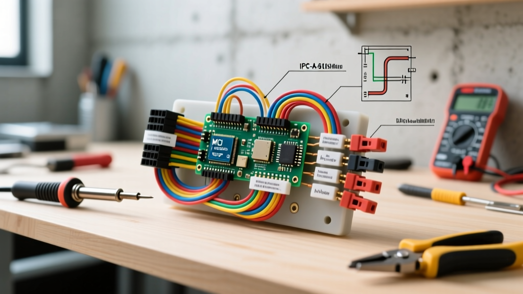

The Critical Role of Safety in Electrical Wiring Harness Design
When engineering custom control panels, heavy machinery, or automotive systems, electrical wiring harness design is often treated as an afterthought—a mere routing exercise to connect point A to point B. This is a dangerous misconception. A poorly designed harness is a primary vector for thermal runaway, arc faults, and catastrophic equipment failure. In 2026, with the increasing density of high-current EV platforms and sensitive IoT telemetry in industrial environments, the margin for error has vanished.
Safety in harness design is not just about selecting the right wire gauge; it encompasses thermal derating, mechanical strain relief, environmental shielding, and precise termination protocols. This guide details the actionable, field-tested safety best practices required to design wiring harnesses that meet or exceed modern industrial and aerospace standards.
Governing Standards: The Baseline for Safe Design
Before routing a single conductor, designers must anchor their schematics to recognized safety frameworks. Relying on generic electrical codes is insufficient for complex harnesses. You must integrate the following standards into your design validation matrix:
- IPC/WHMA-A-620E: The definitive industry standard for cable and wire harness assemblies. It dictates exact visual and mechanical criteria for crimping, soldering, and lacing. You can review the core requirements via the IPC/WHMA-A-620 Standard documentation.
- NFPA 79: The NFPA 79 Electrical Standard for Industrial Machinery mandates specific wire types (e.g., MTW or THHN) and color-coding protocols to prevent miswiring during maintenance.
- OSHA Electrical Safety Guidelines: Ensures that the final harness assembly supports proper lockout/tagout (LOTO) procedures and prevents accidental contact with energized parts, as outlined in OSHA Electrical Safety Guidelines.
Wire Gauge Selection and Thermal Derating
The most common failure mode in harness design is thermal degradation of wire insulation due to ignoring bundle derating. When multiple current-carrying conductors are bundled tightly together, they cannot dissipate heat effectively. If you size your wire based on single-conductor free-air ampacity, the harness will overheat.
Derating Matrix for Bundled Conductors
The following table illustrates the mandatory ampacity derating based on the number of current-carrying conductors in a single harness bundle, utilizing standard 75°C rated cross-linked polyethylene (XLPE) wire.
| AWG Size | Single Wire (Free Air) | 3-6 Wires in Bundle (80% Derating) | 7-24 Wires in Bundle (70% Derating) | 25+ Wires in Bundle (60% Derating) |
|---|---|---|---|---|
| 14 AWG | 15.0 A | 12.0 A | 10.5 A | 9.0 A |
| 12 AWG | 20.0 A | 16.0 A | 14.0 A | 12.0 A |
| 10 AWG | 30.0 A | 24.0 A | 21.0 A | 18.0 A |
| 8 AWG | 40.0 A | 32.0 A | 28.0 A | 24.0 A |
Pro Tip: Always separate high-current power conductors (e.g., 480V VFD feeds) from low-voltage signal wires (e.g., 4-20mA sensor loops) into separate harness branches to prevent electromagnetic interference (EMI) and localized thermal hotspots.
Mechanical Routing: Bend Radii and Chafing Prevention
Mechanical stress compromises insulation integrity, leading to short circuits. The physical routing of the harness must account for dynamic movement, vibration, and sharp chassis edges.
Enforcing Minimum Bend Radii
Violating the minimum bend radius causes micro-fractures in copper stranding and stresses the dielectric insulation. Adhere strictly to these multipliers based on the harness's outer diameter (OD):
- Single Unshielded Wire: Minimum bend radius of 3x the wire OD.
- Shielded Cable / Coaxial: Minimum bend radius of 6x the cable OD to prevent shield braid deformation.
- Multi-Conductor Harness Bundle: Minimum bend radius of 6x to 8x the bundle OD, depending on the stiffness of the outer loom.
Chafing and Edge Protection
Never route a harness directly over an unpainted or sharp metal bulkhead. Vibration will saw through the insulation in a matter of weeks. Actionable Fix: Install split-loom tubing with integrated edge clips, or use HellermannTyton Ratchet P-Clamps lined with EPDM rubber. For pass-throughs in sheet metal, always install a continuous silicone or neoprene grommet (e.g., Essentra Components MSB series) before pulling the harness.
Termination Integrity: The Danger of Cold Crimps
A harness is only as strong as its weakest termination. "Cold crimps"—caused by using mismatched dies, incorrect wire strip lengths, or uncalibrated tooling—result in high-resistance joints that generate immense heat under load.
Crimp Pull-Force Requirements
According to IPC-A-620 and UL 486A standards, crimped connections must withstand specific axial pull forces without the wire separating from the terminal. Below are the minimum pull-test thresholds for standard copper wire:
- 18 AWG: 50 lbs (222 N)
- 16 AWG: 60 lbs (267 N)
- 14 AWG: 80 lbs (356 N)
- 12 AWG: 100 lbs (445 N)
Note: These values apply to the wire-to-terminal interface. If the wire breaks outside the crimp barrel during testing, the crimp is considered acceptable.
Tooling and Validation
Do not rely on generic ratcheting crimpers for high-reliability applications. Utilize application tooling matched exactly to the terminal series. For example, if using Molex Mini-Fit Jr. terminals, you must use the Molex 200218-2100 hand crimp tool or their pneumatic equivalent. Always perform a cross-sectional crimp analysis (micro-sectioning) during the first-article inspection to verify the compression ratio and ensure no voids exist within the crimp barrel.
Environmental Shielding and Thermal Protection
Harnesses operating near heat sources (exhaust manifolds, industrial ovens, or high-wattage resistors) require specialized shielding. Standard PVC insulation begins to degrade and off-gas toxic hydrochloric acid at temperatures exceeding 105°C.
Safety Warning: Never use standard PVC heat-shrink tubing over high-current busbars or power resistors. The trapped heat will melt the PVC, creating a severe fire and toxic fume hazard. Use halogen-free, high-temperature materials instead.
Recommended Shielding Materials:
- FEP (Fluorinated Ethylene Propylene) Heat Shrink: Rated for continuous use up to 200°C. Ideal for tight routing near thermal sources.
- Fiberglass Braided Sleeving with Silicone Coating: Provides exceptional abrasion resistance and withstands intermittent temperatures up to 260°C (500°F).
- Aluminized Mylar Tape: Used for wrapping harness branches that require radiant heat reflection without adding significant bulk or weight.
Pre-Flight Validation: Hi-Pot and Continuity Testing
Visual inspection is insufficient to guarantee the safety of a completed electrical wiring harness. Before installation, every harness must undergo automated testing on a cable tester (such as a Cirris Signature 1100+).
- Continuity Testing: Verifies point-to-point connectivity and ensures no open circuits exist.
- Isolation / Hi-Pot Testing: Applies a high-voltage DC pulse (typically 1000V to 2500V DC for 60 seconds) between adjacent conductors and between the conductors and the shield/chassis. This detects micro-pinholes in the insulation or stray copper whiskers that could cause dielectric breakdown in the field.
- 4-Wire Kelvin Testing: Measures the exact milliohm resistance of the crimped joints to identify high-resistance "cold crimps" that standard continuity tests would miss.
Conclusion: Designing for the Lifecycle
Safe electrical wiring harness design requires a shift in perspective from simple connectivity to holistic lifecycle reliability. By strictly adhering to thermal derating matrices, enforcing mechanical bend radii, utilizing matched-application crimp tooling, and mandating hi-pot validation, engineers can eliminate the root causes of harness-induced electrical fires. In high-stakes industrial and commercial environments, the upfront cost of precision tooling and rigorous testing is infinitesimal compared to the cost of a field failure.