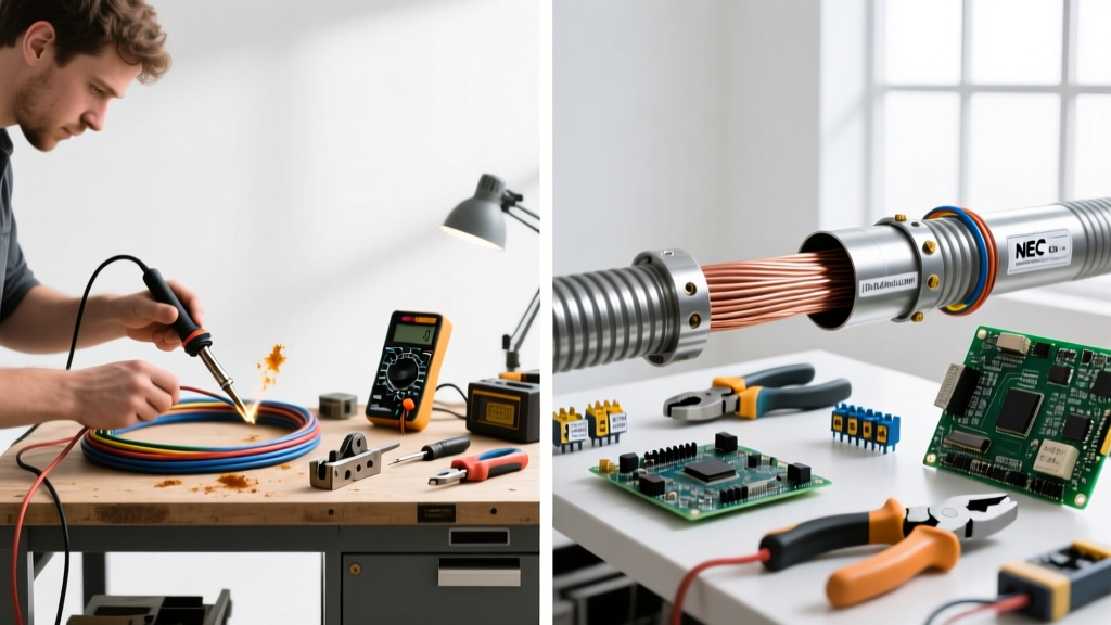
Core Components: Selecting the Right Step-Down Unit
Wiring a transformer for residential or light-commercial applications—such as stepping down 240V to 120V for heavy appliances, workshop machinery, or specialized lighting—requires more than just connecting wires to terminals. The foundation of a safe, code-compliant installation begins with selecting the correct transformer topology and rating. For most modern DIY and prosumer workshops, a 1.5 kVA to 3 kVA single-phase dry-type transformer is the standard. A highly reliable model in this space is the Hubbell Acme T-1-81225-1S (1.5 kVA, 240x480V to 120/240V).
When sourcing your transformer, you must evaluate the K-Factor rating. Standard transformers (K-1) are designed for linear loads like resistive heaters. However, modern environments are saturated with non-linear loads such as Variable Frequency Drives (VFDs), LED drivers, and switching power supplies. These devices generate triplen harmonics (3rd, 9th, 15th) that cause severe eddy current losses and neutral overheating. If your secondary circuit will power CNC routers, welders with inverter technology, or extensive LED arrays, invest in a K-4 or K-13 rated transformer. These units feature derated core flux densities, oversized neutral terminals, and specialized winding geometries to dissipate harmonic heat safely.
The Essential Toolkit for Transformer Termination
The most common point of failure in transformer installations is the terminal connection. Hand-tightening lugs or using standard screwdrivers without torque control leads to micro-arcing, thermal expansion cycles, and eventual catastrophic connection failure. To wire a transformer correctly, your toolkit must include precision termination instruments.
- Wiha 285T6 TorqueVario-S Screwdriver: Transformer terminal screws (typically brass or copper-plated) require precise torque, usually between 25 and 35 inch-pounds (in-lbs). The Wiha 285T6 allows you to dial in the exact manufacturer specification, preventing stripped threads or loose connections.
- Panduit CT-1570 Crimp Tool: Never wrap bare wire around a transformer stud. You must use ring terminals. The CT-1570 provides a full-cycle, ratcheting crimp that ensures a gas-tight connection between the copper conductor and the terminal lug.
- Klein Tools 11055 Wire Stripper: Precision stripping is vital. Nicking the copper conductor reduces its ampacity and creates a hot spot under the lug. This model cleanly strips 10 to 22 AWG solid and stranded wire without scoring the metal.
- FLIR C5 Thermal Imaging Camera: Post-installation verification is a hallmark of professional work. After energizing the transformer and applying a load, scan the primary and secondary terminals. Any temperature delta greater than 5°F (3°C) between phases or at the neutral lug indicates a high-resistance fault requiring immediate re-termination.
Material Breakdown: Conductors, Lugs, and Conduit
Sizing your conductors and lugs correctly is dictated by the transformer's VA rating and the National Electrical Code (NEC). Let us break down the exact materials required for wiring a standard 1.5 kVA (1500 VA) single-phase transformer operating at 240V on the primary and 120V on the secondary.
| Parameter | Primary Side (240V) | Secondary Side (120V) | Grounding / Bonding |
|---|---|---|---|
| Max Current | 6.25 Amps | 12.5 Amps | N/A (Fault Path) |
| Wire Gauge (THHN) | 10 AWG (Black/Red) | 10 AWG (Black/White) | 8 AWG Bare Copper |
| Terminal Lug | Panduit PV10-8R | Panduit PV10-10R | Panduit PV8-8R (or Cadweld) |
| Overcurrent Protection | 15A 2-Pole Breaker | 15A or 20A 1-Pole | N/A |
| Conduit Type | 3/4' EMT or LFMC | 3/4' EMT or LFMC | N/A |
Note: While 14 AWG wire is technically permissible for 6.25A under certain NEC ampacity tables, 10 AWG is the industry standard for transformer pigtails to ensure mechanical strength, minimize voltage drop, and accommodate the physical size of the terminal studs.
The Importance of Insulated Ring Terminals
Always use nylon-insulated ring terminals (like the Panduit PV series) rather than non-insulated vinyl or bare metal lugs. The nylon insulation sleeve extends over the wire's jacket, providing strain relief and preventing the wire strands from fraying and causing short circuits against the transformer chassis. Furthermore, the insulated sleeve acts as a secondary barrier against accidental contact with the energized stud during maintenance.
The Separately Derived System (SDS) Grounding Dilemma
One of the most heavily cited NEC violations when wiring a transformer involves the secondary neutral. When you wire a transformer that creates a new 120V system from a 240V primary (which has no neutral), you are creating a Separately Derived System (SDS). According to NFPA NEC Article 250.30, an SDS requires its own grounding electrode system and a specific bonding jumper.
NEC Code Spotlight: You must bond the secondary neutral (the X0 terminal) to the transformer chassis (Equipment Grounding Conductor) AND install a System Bonding Jumper (SBJ) sized according to NEC Table 250.102(C)(1). For a 1.5 kVA transformer, this typically requires an 8 AWG copper bonding jumper connecting the X0 terminal directly to the ground busbar or chassis ground lug. Failure to do this leaves the secondary circuit floating, meaning a ground fault will not trip the breaker, creating a lethal shock hazard.
To execute this, you will need a Cadweld ground kit or a dedicated grounding busbar (e.g., Siemens GBK4) mounted inside or immediately adjacent to the transformer enclosure, alongside an 8 AWG bare copper grounding electrode conductor routed to a grounding rod or building steel.
Step-by-Step Material Prep and Termination Sequence
- Conductor Prep: Strip exactly 1/2 inch of insulation from the 10 AWG THHN wire using the Klein Tools 11055. Inspect the strands for any nicks; if damaged, cut and re-strip.
- Crimping: Slide the wire into the Panduit PV10-8R ring terminal until the strands are flush with the inspection hole. Use the Panduit CT-1570 crimp tool on the correct die setting (usually marked for #10 insulated). The ratchet will not release until the crimp is fully compressed.
- Heat Shrink (Optional but Recommended): For environments with high vibration or dust, slide a piece of 3M 1/4-inch adhesive-lined heat shrink over the terminal neck before crimping, and apply heat after crimping to seal out moisture.
- Torquing: Place the ring terminal over the transformer stud, followed by the provided lock washer and brass nut. Set your Wiha torque screwdriver to the manufacturer's specification (typically 30 in-lbs for Acme/Hubbell units). Tighten until the driver clicks.
- Secondary Bonding: Install the System Bonding Jumper from the X0 terminal to the grounding busbar. Torque to the same specification.
Common Failure Modes and Material Defects
Even with the right tools, material defects or environmental factors can compromise the installation. Understanding these failure modes is critical for long-term reliability.
1. Harmonic Overheating and Insulation Degradation
If a standard K-1 transformer is used to power a server rack or a bank of LED grow lights, the triplen harmonics will circulate in the delta primary winding and add up in the wye secondary neutral. This causes the transformer core to overheat, eventually degrading the polyimide insulation on the windings. This leads to inter-turn short circuits and catastrophic failure. Solution: Always audit the load profile and upgrade to a K-13 transformer if non-linear loads exceed 30% of the total VA.
2. Galvanic Corrosion at Terminal Lugs
If you use aluminum-rated lugs (AL9CU) on copper transformer studs in a humid environment (like an unconditioned garage or agricultural facility), galvanic corrosion will occur. This increases the resistance of the joint over time, generating immense heat. Solution: Strictly use copper-only (CU) lugs for transformer terminations, and apply a light coat of Noalox antioxidant paste only if specifically permitted by the transformer manufacturer's documentation (many modern dry-type units forbid paste as it can attract dust and reduce clearances).
3. Conduit Fill and Heat Dissipation
Transformers generate heat. Routing conductors through tightly packed, undersized conduit limits the wire's ability to shed heat, requiring severe ampacity derating under NEC Chapter 9, Table 1. Solution: Keep conduit fill below 40% and use Liquid-Tight Flexible Metal Conduit (LFMC) with insulated bushings to allow for vibration damping and adequate heat dissipation.
Sourcing and Budget: What to Expect
Building a professional-grade transformer termination kit requires an upfront investment, but it prevents thousands of dollars in potential fire damage and equipment loss. A genuine 1.5 kVA Hubbell Acme transformer will cost between $250 and $400 depending on the K-factor and enclosure type (NEMA 1 vs. NEMA 3R). The specialized tooling (Wiha torque driver and Panduit crimp tool) will add approximately $150 to $200 to your budget. However, these tools are lifetime investments that will be utilized across every panel upgrade, subpanel installation, and heavy appliance circuit you build in the future.
For further reading on transformer overcurrent protection and tap changer adjustments, consult the Hubbell Acme Transformer Installation Guides and the extensive technical library at Mike Holt Enterprises. Proper material selection and disciplined tool usage are the only ways to ensure your step-down transformer operates safely for decades.