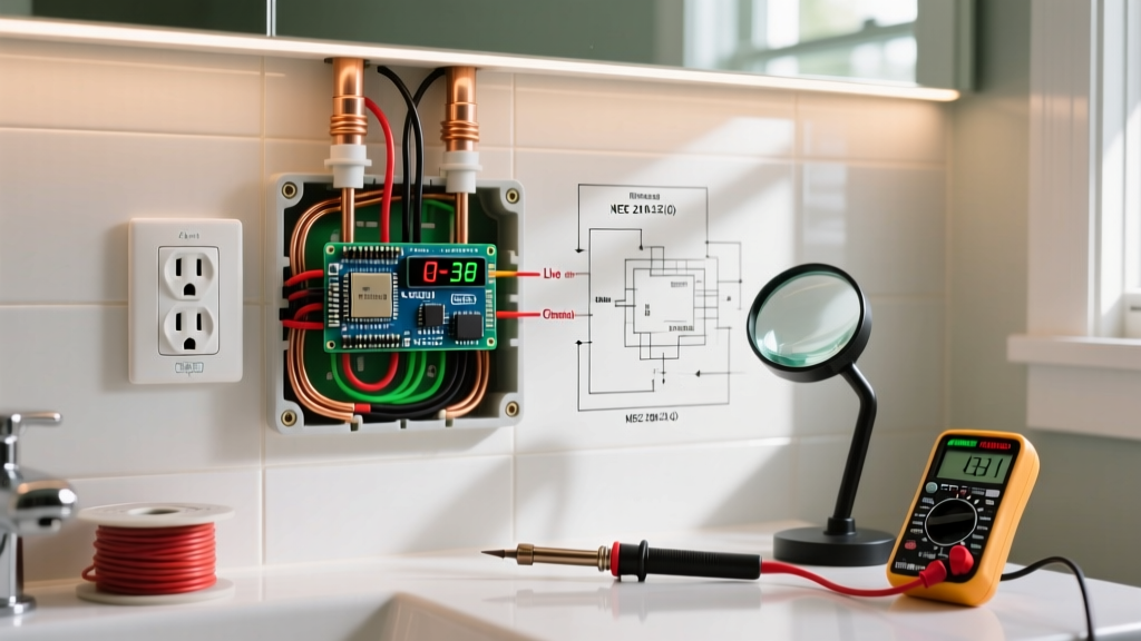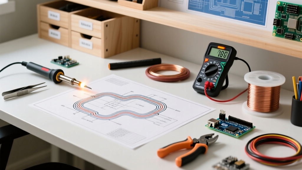

Creating, reading, and executing an accurate electrical wiring blueprint is the foundational step in any successful residential, commercial, or industrial electrical project. Whether you are mapping out a 120/240V single-phase residential service or a complex 480V three-phase commercial distribution system, the blueprint serves as the universal language between the engineer, the electrician, and the building inspector. In 2026, the transition from hand-drafted vellum schematics to fully integrated Building Information Modeling (BIM) and cloud-based field management has revolutionized how electrical professionals interact with plans.
However, the digital shift does not eliminate the need for physical materials, specialized field tools, and a deep understanding of drafting standards. This comprehensive material and tool guide breaks down exactly what you need to draft, print, and execute an electrical wiring blueprint with precision.
Digital Drafting Software for Electrical Blueprints
The modern electrical wiring blueprint begins in a digital environment. Selecting the right Computer-Aided Design (CAD) or BIM software dictates your workflow efficiency, symbol library accuracy, and ability to perform automated load calculations. Below is a comparison of the industry-standard software platforms used by electrical engineers and designers in 2026.
| Software Platform | Best Application | 2026 Pricing (Approx.) | Key Electrical Feature |
|---|---|---|---|
| AutoCAD Electrical | Industrial Control Panels & Commercial Wiring | $1,955 / year | Automated wire numbering and BOM generation |
| Revit MEP | Large Commercial BIM & 3D Coordination | $2,945 / year | Clash detection with HVAC and plumbing |
| Chief Architect Premier | Residential Wiring & Remodels | $2,995 (Perpetual) | Auto-generated residential lighting schedules |
| SmartDraw Electrical | Quick Schematics & DIY Blueprints | $119 / year | Drag-and-drop IEEE/ANSI symbol libraries |
For professionals adhering to the US National CAD Standard (NCS), layer management is critical. Your electrical wiring blueprint should utilize standardized layer prefixes such as E-POWER for receptacles and equipment, E-LITE for lighting, and E-CTRL for control wiring. This ensures seamless collaboration with architectural and structural teams.
Physical Drafting Tools & Field Markup Materials
Despite the dominance of CAD, physical redlining and manual drafting remain essential skills, particularly for field modifications, as-built drawings, and quick conceptual sketches on the job site. Equipping your mobile drafting kit with the right materials ensures your markups are legible, permanent, and professional.
Essential Redline and Drafting Pens
- Sakura Pigma Micron Archival Ink Pens: The industry standard for blueprint markups. Use the 01 (0.25mm) nib for routing low-voltage control wires and the 05 (0.45mm) nib for heavy feeder lines. The archival ink prevents fading when exposed to UV light on the job site.
- Staedtler Lumocolor Non-Permanent Markers: Ideal for temporary markups on laminated blueprints or tablet screen protectors. The chisel tip allows for both broad circuit highlighting and fine-point annotations.
- Rotring Isograph Technical Pens: For manual drafting on vellum, a 0.35mm or 0.50mm technical pen provides the exact line weights required by NEC and architectural drafting standards.
Scales, Templates, and Vellum
When verifying physical dimensions against an electrical wiring blueprint, a standard tape measure is insufficient. You need an architectural scale ruler (typically 1/4' = 1'-0' for residential floor plans and 1/8' = 1'-0' for commercial sites). For manual drafting, use 24-inch x 50-yard rolls of 16lb translucent vellum. Vellum allows for easy erasing and layered tracing over architectural base plans without bleeding ink.
Expert Tip: Never use standard ballpoint pens for field redlines on standard blueprint paper. The pressure required to write with a ballpoint often tears the 20lb bond paper, and the oil-based ink can smear when exposed to job-site humidity or sweat, rendering crucial circuit modifications illegible.
Blueprint Printing and Reproduction Materials
Translating your digital CAD files into physical, job-ready blueprints requires specialized large-format printing materials. The choice of paper weight and finish directly impacts the durability of the blueprint in harsh construction environments.
Plotter Paper Selection Guide
- 20lb Standard Bond (Matte): The most economical choice for internal reviews and preliminary drafts. It is lightweight and easy to fold into standard ANSI D (22' x 34') or ANSI E (34' x 44') sizes. However, it tears easily on active job sites.
- 32lb Bright White Inkjet: The premium standard for final issued-for-construction (IFC) blueprints. The heavier weight resists tearing, and the bright white coating ensures that fine, light-gray architectural background lines do not overpower the bold black electrical circuit lines.
- Tyvek Synthetic Paper: For extreme environments (e.g., marine electrical wiring, outdoor substations, or high-humidity commercial kitchens). Tyvek is completely waterproof, tear-proof, and accepts specialized solvent-based plotter inks.
To print these materials, firms typically rely on large-format plotters like the HP DesignJet T650 24-inch (priced around $2,199 in 2026) or the Canon imagePROGRAF PRO-2100 for high-contrast, color-coded BIM outputs.
Decoding Blueprint Symbols and NEC Standards
An electrical wiring blueprint is only as good as the electrician's ability to read its symbols. In the United States, electrical symbols are governed by a combination of NFPA 70 (National Electrical Code) requirements and ANSI Y32.2 / IEEE 315 graphic symbol standards.
When drafting or reading a blueprint, pay close attention to these critical symbol variations:
- Receptacles: A standard circle with two parallel lines indicates a standard 15A/20A 120V duplex receptacle. A circle with 'G' or 'GFCI' inside denotes Ground Fault Circuit Interrupter protection, mandated by the 2026 NEC for all bathrooms, kitchens, and outdoor areas.
- Switches: A standard 'S' denotes a single-pole switch. An 'S' with a subscript '3' or '4' indicates 3-way or 4-way traveler configurations. A '$' symbol inside the switch circle designates a dimmer switch.
- Home Runs: A line with an arrow pointing toward the panel schedule indicates a 'home run'—the physical conduit routing back to the main distribution board. The number of slashes across the line indicates the number of current-carrying conductors in that specific raceway.
Field Execution: Taking the Blueprint to the Job Site
The final phase of the blueprint lifecycle is field execution. In 2026, carrying massive rolls of paper is increasingly being replaced by ruggedized digital field management, though physical backups remain a code-required necessity in many jurisdictions.
Digital Field Management Hardware
To interact with digital blueprints on site, electricians utilize rugged tablets. The Panasonic Toughbook G2 remains the gold standard for industrial environments, offering sunlight-readable screens and MIL-STD-810H drop resistance. For residential and light commercial contractors, the Apple iPad Pro 12.9-inch housed in an OtterBox Defender Series case provides a cost-effective alternative with access to powerful blueprint management apps like Procore and PlanGrid.
Precision Measurement Tools
Verifying conduit routing distances and panel clearances requires more than a standard tape measure. The Bosch GLM 50 C Laser Distance Measure ($149) allows electricians to instantly measure distances up to 165 feet with 1/16-inch accuracy. Crucially, the GLM 50 C features Bluetooth connectivity, allowing you to beam measurements directly into your digital blueprint app to verify that the physical space matches the drafted electrical wiring blueprint before bending and cutting expensive EMT or rigid conduit.
Frequently Asked Questions (FAQ)
What is the standard scale for a residential electrical wiring blueprint?
The standard scale for residential electrical floor plans is 1/4 inch = 1 foot. This scale provides enough detail to accurately place receptacles, switches, and lighting fixtures relative to doors, windows, and structural walls. Commercial plans often use 1/8 inch = 1 foot due to the larger square footage of the buildings.
Do I need a licensed engineer to draft an electrical blueprint?
For standard residential wiring, a licensed master electrician or a qualified electrical designer can draft the blueprint, provided it meets local building codes and NEC requirements. However, for commercial, industrial, or multi-family dwellings exceeding specific load thresholds, most jurisdictions require the blueprint to be stamped and sealed by a licensed Professional Engineer (PE).
How often should blueprints be updated during a project?
Blueprints should be treated as living documents. Any field changes made during rough-in or trim-out must be marked in red (redlined) on the master set daily. Upon project completion, these redlines must be incorporated into the CAD file to generate the final As-Built electrical wiring blueprint, which is handed over to the building owner for future maintenance and troubleshooting.