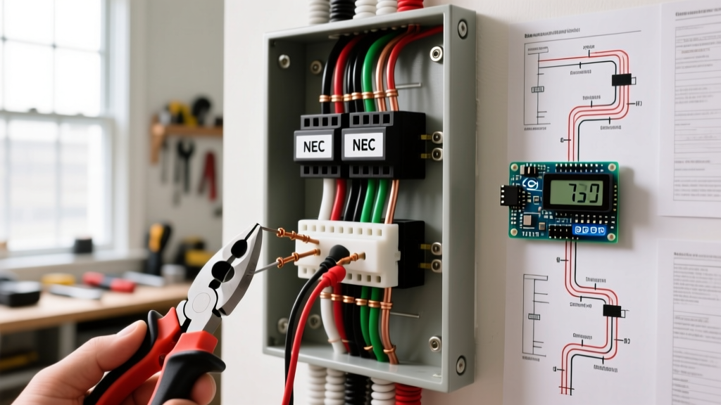
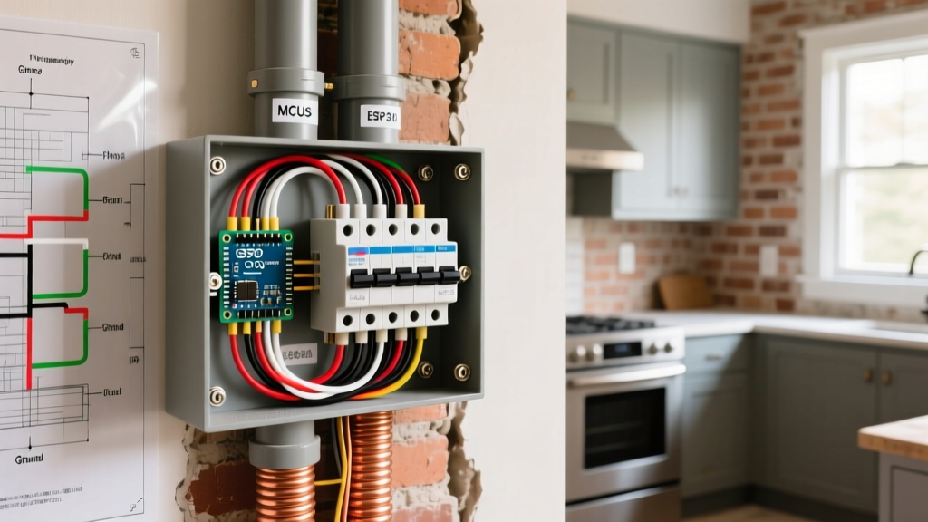
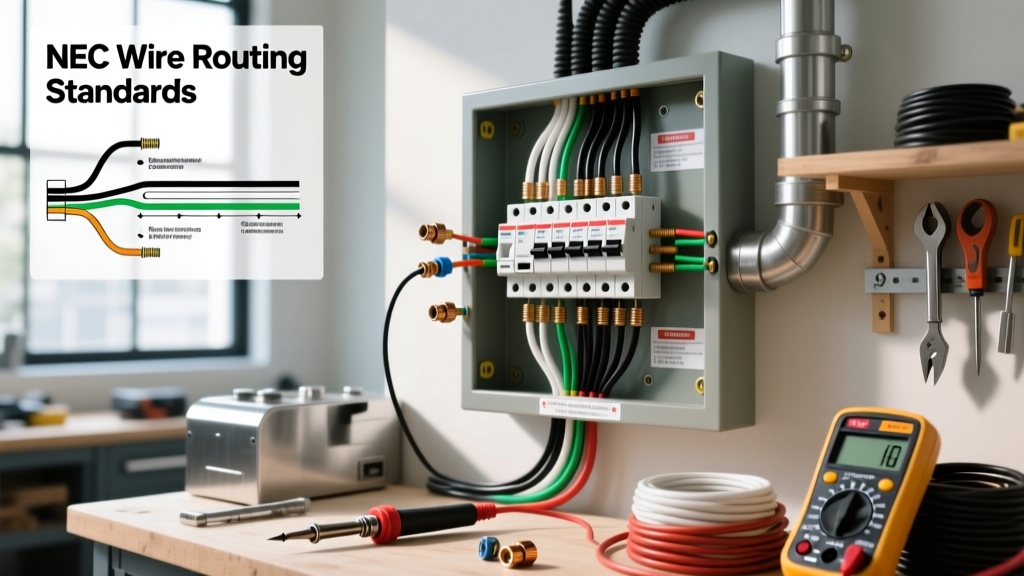
Electric socket wiring is the physical connection of branch circuit conductors to a receptacle's terminal screws or push-in clamps to deliver line voltage to a plug-in load. When executed correctly, this wiring topology dictates whether a circuit maintains downstream power during a device failure, ensures the grounding path remains intact under fault conditions, and prevents thermal runaway at the termination points. Beginners and even some tradespeople commonly confuse "feed-through" (daisy-chaining) wiring with "pigtailing," or they dangerously mix up the LINE and LOAD terminals on GFCI receptacles, assuming they are interchangeable standard hot/neutral pairs.
The Core Mechanics: Terminals, Torque, and Polarity
At the workbench or on the jobsite, a standard 15A or 20A NEMA 5-15R or 5-20R receptacle presents three distinct termination zones. The brass-colored screws terminate the ungrounded (hot) conductor, the silver-colored screws terminate the grounded (neutral) conductor, and the green screw terminates the equipment grounding conductor (EGC). Reversing the hot and neutral—known as reverse polarity—won't stop a standard lamp from turning on, but it leaves the internal switching mechanisms of appliances energized even when turned off, creating a severe shock hazard during maintenance.
According to NFPA 70 (National Electrical Code) Section 110.14(D), terminations must be torqued to the manufacturer's specifications. For a standard commercial-grade receptacle like the Leviton T5262-W, the brass and silver terminal screws require exactly 14 in-lbs of torque when terminating 12 AWG solid copper wire. Undertorquing leads to high-resistance connections that arc and melt the plastic yoke; overtorquing strips the screw threads or slices through the copper conductor, reducing its ampacity.
Where You Meet This In Practice
You will encounter specific electric socket wiring scenarios depending on the room and the load profile. In kitchen small-appliance branch circuits, NEC 210.11(C)(1) requires at least two 20A circuits wired with 12 AWG conductors. Here, you must use 20A-rated receptacles (which accept both 15A and 20A plugs) and ensure the break-through fin on the brass (hot) side remains intact unless you are intentionally splitting the receptacle for a multi-wire branch circuit (MWBC).
In living areas and bedrooms, you are typically dealing with 15A general-purpose circuits using 14 AWG NM-B cable. This is where you frequently encounter the need to replace standard receptacles with Tamper-Resistant (TR) models, as mandated by NEC 406.12. When upgrading older homes, you will also meet the challenge of missing equipment grounds. In these cases, you are permitted to install a GFCI receptacle to provide shock protection, but you must label it "No Equipment Ground" and you cannot use the LOAD terminals to protect downstream ungrounded sockets without careful consideration of the fault current path.
Worked Numeric Example: NEC Box Fill for a 20A Receptacle
One of the most frequent failures in residential wiring is overcrowding an electrical box, which traps heat and damages wire insulation. Let's calculate the exact box fill required when adding a new 20A duplex receptacle to an existing bedroom run, following OSHA and NEC Article 314.16(B) guidelines.
The Scenario: You have a standard 4x2 inch electrical box. Entering the box is one existing 12/2 NM-B cable (the feed) and one new 12/2 NM-B cable (feeding the next socket). The box has internal cable clamps.
- Conductor Volume: 12 AWG wire requires 2.25 cubic inches per conductor. You have 2 hot wires and 2 neutral wires (4 total). 4 × 2.25 = 9.0 cu in.
- Grounding Conductor Volume: All equipment grounding conductors in a single box count as a single volume allowance based on the largest ground present. 1 × 2.25 = 2.25 cu in.
- Clamp Volume: Internal clamps count as one volume allowance. 1 × 2.25 = 2.25 cu in.
- Device Yoke Volume: The receptacle itself counts as two volume allowances. 2 × 2.25 = 4.5 cu in.
Total Required Volume: 9.0 + 2.25 + 2.25 + 4.5 = 18.0 cubic inches.
A standard shallow 4x2x1.5 inch box only holds 12.5 cubic inches. A standard deep 4x2x2.125 inch box holds 18.0 cubic inches, which is exactly at the legal limit. To give yourself physical room to fold 12 AWG wires without stressing the terminal screws, you should install a 4x2x2.5 inch box (21.0 cu in capacity). As noted by the Department of Energy's home electrical guidelines, proper heat dissipation relies on this physical air space inside the enclosure.
Pigtailing vs. Feed-Through: Which Topology to Choose?
When wiring multiple sockets on a single branch circuit, you must choose between feed-through (daisy-chaining) and pigtailing. In feed-through wiring, the incoming hot and neutral wires connect to one set of terminal screws, and a second set of wires connects to the opposite screws to feed the next device. In pigtailing, you use wire nuts or push-in connectors (like Wago 221s) to join the incoming and outgoing wires with a short 6-inch "pigtail" that runs to the receptacle.
| Criteria | Feed-Through (Daisy-Chain) | Pigtailing |
|---|---|---|
| Downstream Continuity | Lost if the receptacle fails or is removed. | Maintained; downstream sockets stay live. |
| Box Fill Impact | Lower (no extra wire nuts or pigtails). | Higher (adds 3+ conductors and connectors). |
| MWBC Compatibility | Dangerous; breaking the neutral breaks the return path for the other phase. | Mandatory; keeps the multi-wire neutral intact. |
| Installation Speed | Faster; fewer wire stripping and twisting steps. | Slower; requires making up splices before terminating. |
The Verdict: Always pigtail your neutral wires, especially on multi-wire branch circuits, to prevent overloading the shared neutral if the receptacle is removed. For standard single-phase 15A circuits in dry locations, feed-through is code-compliant and widely used, but pigtailing remains the hallmark of a high-reliability installation.
Frequently Asked Questions
Can I use the push-in backwire holes on a standard 15A receptacle?
While NEC permits the use of listed push-in (backstab) terminals for 14 AWG solid copper wire on 15A receptacles, they are notoriously unreliable in high-vibration or high-thermal-cycling environments. The internal spring-steel clamps can lose tension over time, leading to arcing. For a permanent, trouble-free installation, strip the wire to the gauge marker on the back of the yoke and use the side terminal screws, looping the wire clockwise so the tightening action pulls the loop tighter.
What happens if I wire the hot and neutral in reverse on an electric socket?
Reverse polarity will allow most standard loads (like lamps or phone chargers) to operate normally because AC current alternates direction. However, it creates a severe shock hazard. In a correctly wired socket, the neutral blade is bonded to the appliance chassis or the outer sleeve of a lamp bulb socket. If reversed, touching the outer sleeve of a lightbulb while changing it, or touching the metal chassis of a faulted appliance, completes the circuit to ground through your body.
Do I need to pigtail the ground wire if I am replacing an old two-prong socket?
If you are upgrading a two-prong ungrounded receptacle to a three-prong GFCI receptacle (permitted by NEC 406.4(D)(2) when no equipment ground exists), you do not pigtail a ground wire to the green screw because there is no ground wire in the wall. You must connect the LINE hot and neutral, leave the green screw empty, and apply the included "No Equipment Ground" sticker to the faceplate. If an equipment ground does exist in the box (e.g., via metal conduit or a bare copper wire), you must absolutely pigtail it to the receptacle's green screw and the metal box if present.
Why did my downstream outlets lose power when I replaced a standard receptacle?
This almost always happens because the previous installer used the feed-through method, and during your replacement, you either failed to connect the downstream wires to the new receptacle, or you accidentally broke the brass/neutral connecting fin on the side of the new device. Furthermore, if you mistakenly wired the incoming power to the LOAD terminals instead of the LINE terminals on a GFCI receptacle, the internal relay will not energize the downstream circuit until the GFCI is manually reset, and it may trip immediately under load.