
The Hidden Fire Hazard in Aftermarket Carburetors
When swapping to an aftermarket carburetor like the Edelbrock Performer Series (models 1406, 1411, or 1906), converting to an electric choke is a standard upgrade for improved cold-start drivability. However, as of 2026, SEMA-recognized tech inspection guidelines and strict NHRA safety techs have heavily cracked down on improper Edelbrock electric choke wiring. What many hobbyists consider a 'quick fix'—tapping into the ignition coil or alternator stator—is now an automatic failure at tech inspection and a severe under-hood fire hazard.
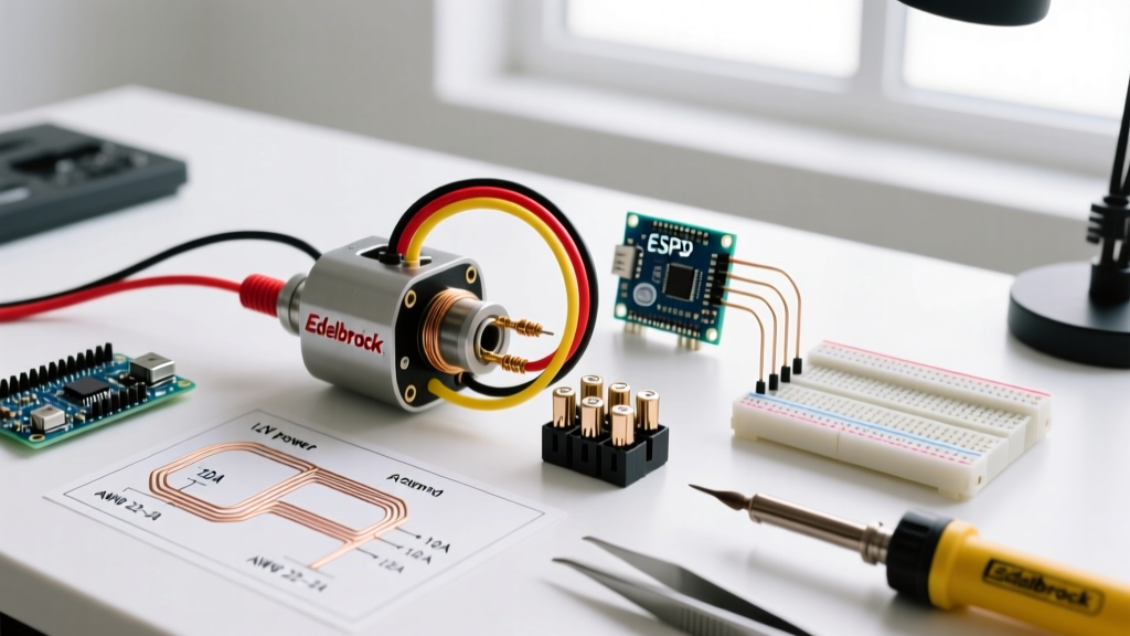
The electric choke cap (such as the Edelbrock #1932 conversion kit) relies on a bimetallic spring that requires a precise, regulated 12V DC signal to heat up and pull the choke lever off the high-idle cam. Supplying the wrong voltage, using non-compliant wire insulation, or failing to establish a dedicated ground path will result in melted plastic housings, stranded vehicles, or electrical fires. This guide details the exact inspection-compliant methodology for wiring an Edelbrock electric choke, ensuring your build passes tech inspection and operates reliably for years.
Why Tech Inspectors Reject 'Hack' Choke Wiring
Tech inspectors are trained to look for three specific violations when evaluating aftermarket carburetor wiring. Understanding these failure modes is critical for compliance.
| Common Violation | Technical Consequence | Inspection Result |
|---|---|---|
| Ignition Coil Tap | Wiring to the coil positive or negative terminal introduces voltage drops during dwell and causes severe EMI interference with modern digital tachometers and EFI triggers. | Automatic Fail (Fire/EMI Risk) |
| Alternator Stator Tap | The stator terminal outputs unregulated AC/DC spikes that can exceed 16V. This overvolt condition melts the Edelbrock cap's plastic housing and degrades the bimetallic spring. | Automatic Fail (Overvoltage Hazard) |
| Unfused Circuits | Running a direct 12V line from the battery or ignition switch without an inline fuse within 6 inches of the source violates basic automotive electrical safety codes. | Automatic Fail (Short Circuit Risk) |
Inspector's Note: According to the official NHRA Rulebook, all aftermarket electrical accessories mounted in the engine compartment must be independently fused and routed using automotive-grade, high-temperature insulation. Bare copper or household THHN wire is strictly prohibited.
The Anatomy of a Compliant Edelbrock Choke Circuit
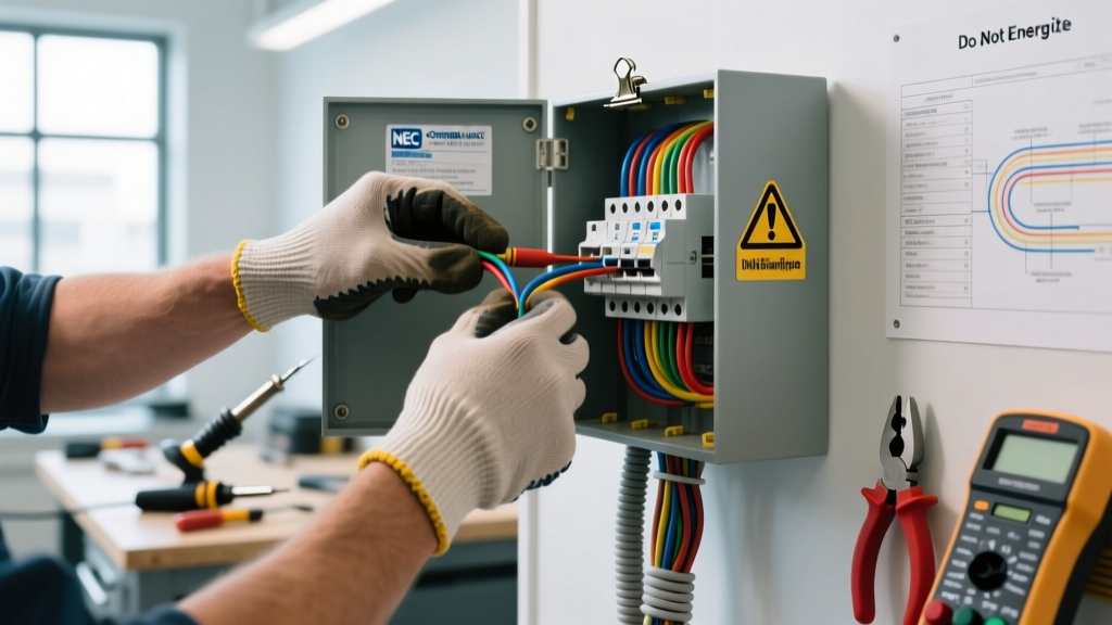
A tech-compliant circuit requires four specific elements: a switched 12V source, proper SAE-rated wire, inline overcurrent protection, and a verified ground path. Let us break down the exact specifications required for the Edelbrock #1932 cap and similar Performer Series models.
1. Sourcing the Correct 12V Signal
The choke heating element requires a 12V signal that is only active when the ignition key is in the 'RUN' or 'ON' position. It must not have power during the 'START' (cranking) phase, nor should it retain power when the key is off. The most compliant method is to use a dedicated auxiliary terminal on your fuse block labeled 'IGN' or 'ACC', or to trigger a standard 30A automotive relay using a low-amp ignition-switched signal, feeding the choke directly from the battery through the relay's high-amp contacts.
2. SAE J1128 Wire Insulation Standards
Standard PVC primary wire (often found in bulk rolls at hardware stores) is rated for 105°C. Under-hood ambient temperatures near an Edelbrock Victor Jr or Performer RPM intake manifold routinely exceed 120°C, especially after heat soak. Tech inspectors require wire that meets the SAE J1128 standard for under-hood wiring, specifically GXL (General Cross-Linked) or TXL insulation. GXL wire features cross-linked polyethylene insulation rated to 125°C (and up to 150°C for short spikes), resisting melting, brittleness, and chemical degradation from under-hood fluids.
3. The Phenolic Spacer Ground Trap
This is the most common reason a perfectly wired Edelbrock choke fails to operate, leading to frustrated builders and failed diagnostics. The Edelbrock electric choke cap grounds through its mounting screws, into the carburetor body, through the base flange, and into the intake manifold.
If you are using a phenolic carburetor spacer (such as Edelbrock #9266) to reduce fuel percolation and prevent vapor lock, you have electrically isolated the carburetor from the engine block. Phenolic resin is an insulator. Without a ground path, the choke cap will not heat up, and the engine will flood on cold starts. Compliance Fix: You must crimp a ring terminal to a dedicated 16 AWG ground wire, attach it to one of the choke cap's mounting screws, and route it directly to a clean, unpainted bolt on the engine block or cylinder head.
Step-by-Step: SAE-Compliant Wiring Procedure
Follow this exact sequence to ensure your wiring harness meets rigorous tech inspection standards.
- Measure and Cut GXL Wire: Measure the distance from your fuse panel's IGN-switched terminal to the carburetor. Add 12 inches for service loops and routing flexibility. Cut a length of 16 AWG GXL wire.
- Install Inline Overcurrent Protection: Crimp an ATO/ATC blade fuse holder onto the positive wire. Install a 5-Amp fuse. The Edelbrock choke heating element draws approximately 1.5 to 2.5 Amps. A 5A fuse provides adequate headroom for inrush current while protecting the 16 AWG wire from melting in the event of a dead short. Place this fuse within 6 inches of the power source.
- Route and Loom: Route the wire along the factory wiring harness, avoiding exhaust headers and sharp firewall edges. Use split-loom tubing or Tesa tape to protect the wire from abrasion and radiant heat.
- Terminate the Choke Connection: The Edelbrock cap typically uses a spade terminal or a specific bayonet connector. Use a high-quality, heat-shrink-sealed crimp terminal (not a bare metal open-barrel crimp) to prevent moisture ingress and corrosion.
- Establish the Dedicated Ground: If a phenolic spacer is present, or if the intake manifold is painted/powder-coated, run a dedicated 16 AWG ground wire from the cap's grounding tab to the engine block.
Choke Circuit Sizing & Compliance Matrix
Use the following matrix to verify your component selection against automotive electrical standards.
| Component | Specification | Compliance Rationale |
|---|---|---|
| Wire Gauge | 16 AWG (or 14 AWG) | 16 AWG safely handles up to 10A; choke draws ~2A. Provides mechanical durability. |
| Wire Insulation | GXL or TXL (SAE J1128) | Cross-linked polyethylene withstands 125°C+ under-hood heat soak without melting. |
| Overcurrent Protection | 5A ATO/ATC Blade Fuse | Protects circuit from dead shorts; sized at ~200% of continuous 2.5A max draw. |
| Power Source | Ignition-Switched 12V (RUN) | Prevents battery drain when parked; avoids cranking voltage drop issues. |
| Ground Path | Dedicated 16 AWG to Block | Bypasses phenolic spacers, painted flanges, and dirty intake mating surfaces. |
Diagnostic Testing: Verifying the Heating Element
Before finalizing your harness and submitting your vehicle for tech inspection, you must verify the integrity of the Edelbrock choke cap itself. According to Edelbrock's official carburetor technical documentation, a failing heating element will cause severe drivability issues that mimic tuning problems.
Multimeter Resistance Specifications
Disconnect the wiring harness from the choke cap. Set your digital multimeter to the Ohms (Ω) setting. Place one probe on the cap's power terminal and the other on the cap's metal housing (ground).
- Normal Reading: 6.0 to 12.0 Ohms at room temperature (70°F). This indicates a healthy bimetallic heating coil.
- Infinite / OL Reading: The internal heating wire is broken. The cap is dead and must be replaced (Edelbrock part #1932).
- Near Zero (0.1 - 1.0 Ohms): The internal coil is shorted to the housing. This will immediately blow your 5A inline fuse upon key-on.
Voltage Drop Testing Under Load
With the engine running and the alternator charging (typically 13.8V - 14.4V), back-probe the choke cap terminal with your multimeter set to DC Volts. You should read within 0.2V of the battery voltage. If you read 11.5V or lower at the cap while the battery reads 14.2V, you have excessive voltage drop. This is usually caused by undersized wire, a corroded firewall bulkhead connector, or a poor ground path through the engine mounts. Tech inspectors will flag a voltage drop greater than 3% (approx. 0.4V on a 14V system) as a failing circuit.
Summary Checklist for the Tech Inspector
When presenting your vehicle for inspection, be prepared to demonstrate the following to the tech official:
- Verification of GXL/TXL wire insulation markings.
- Physical location of the 5A inline fuse within 6 inches of the power source.
- Confirmation that the power source de-energizes when the key is removed.
- Presence of a dedicated ground wire if a phenolic carburetor spacer is installed.
By adhering strictly to these SAE and NHRA-aligned standards, your Edelbrock electric choke wiring will not only pass the most rigorous tech inspections but will also provide flawless, reliable cold-start performance regardless of ambient temperature or under-hood heat soak.