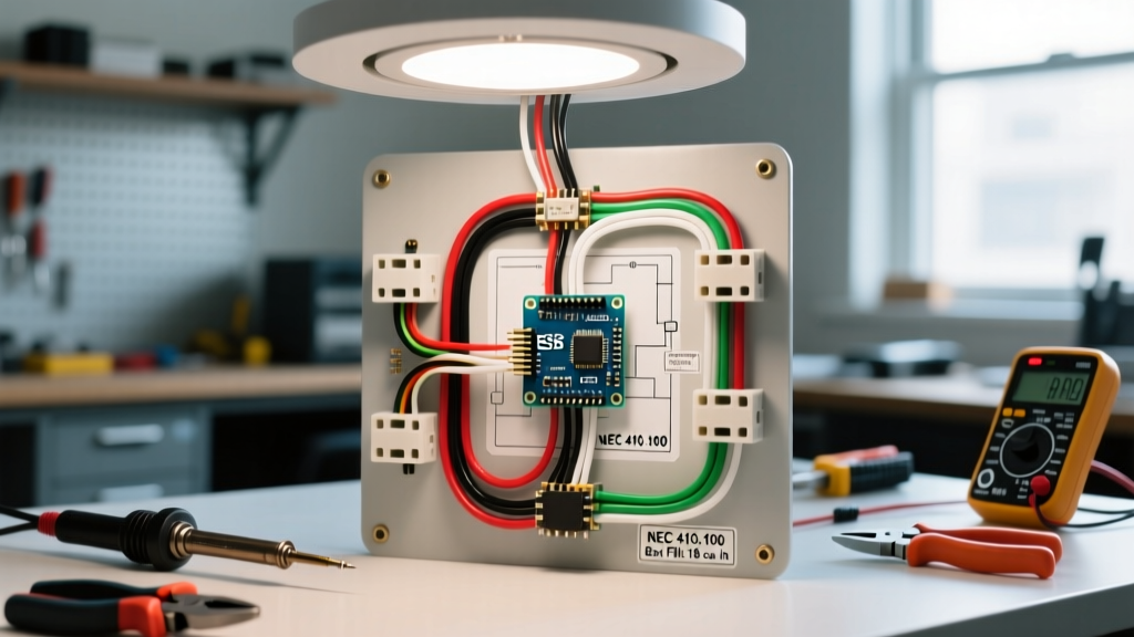
Class A fire alarm wiring is a redundant circuit topology where wires loop out from the control panel to all devices and return back to the panel, ensuring the system remains operational even if a single wire is severed. When you are designing or installing life safety systems, an open circuit—a broken or disconnected wire—is the ultimate enemy. In a standard radial circuit, a single cut kills every device downstream of the break. Class A solves this vulnerability by creating a continuous loop, giving the electrical current a secondary path back to the fire alarm control panel (FACP) if the primary path is compromised.
How Class A Changes the Physical Installation
Choosing Class A over the more common Class B fundamentally changes how you pull wire, terminate connections, and calculate material costs. Instead of running a single 2-conductor cable from the panel to the last device and stopping, you must run a second 2-conductor cable (or a 4-conductor cable) from the last device all the way back to the FACP. This effectively doubles your copper footprint for that specific circuit.
Here is how the standard NFPA 72 circuit classes compare in the field:
| Feature | Class B (Standard) | Class A (Redundant) | Class X (High-Rise) |
|---|---|---|---|
| Topology | Radial (Dead-end) | Loop (Out and Return) | Loop with device isolation |
| Wire Paths | 1 path to devices | 2 paths to devices | 2 paths + isolators between every device |
| Single Open Fault | Devices downstream fail | All devices remain operational | All devices remain operational |
| Supervision Method | End-of-Line (EOL) Resistor | Panel return terminals / Module | Panel return + Isolator modules |
| Material Cost | Lowest | ~2x wire cost of Class B | Highest (wire + isolator modules) |
Think of a Class B circuit like a dead-end cul-de-sac: if a utility pole falls and blocks the only road in, the houses at the end get no supplies. Class A is a loop road connecting to two different main streets; if one entrance is blocked, supplies just route through the other entrance.
The Math: Wire Length, Voltage Drop, and Fault Tolerance
To understand what Class A changes in a real installation, we need to look at the math during a fault condition. Let us calculate the voltage drop for a Notification Appliance Circuit (NAC) powering four ADA-compliant horn/strobes (such as the System Sensor SpectrAlert Advance P2R-W). Each device draws 135mA at 24VDC. Total circuit current is 540mA (0.54A).
The Setup:
- Run distance: 800 feet from the FACP to the furthest device.
- Wire used: 14 AWG FPLR (Resistance is approximately 2.52 Ω per 1,000 ft at 75°C).
- Panel output: 24VDC nominal.
Normal Operation (No Fault):
In a Class B setup, the current travels 800 feet out and 800 feet back on the same pair, totaling 1,600 feet of wire.
Voltage Drop = Current × Resistance = 0.54A × (1.6 × 2.52Ω) = 2.17V.
Operating Voltage at the last device = 24V - 2.17V = 21.83V. (Well above the 16V minimum required by the manufacturer).
The Fault Condition (Wire severed at 400 feet):
A forklift snags the ceiling grid and cuts the cable at the 400-foot mark.
- Class B Result: The circuit is broken. Devices located at 400ft, 600ft, and 800ft receive 0V. The system fails to notify occupants in those zones.
- Class A Result: The FACP detects the open on the primary path and automatically routes power through the return loop. The furthest device (at 800ft) is now powered via 800 feet out, plus 400 feet back to the break point, totaling 1,200 feet of active wire.
Voltage Drop = 0.54A × (1.2 × 2.52Ω) = 1.63V.
Operating Voltage = 24V - 1.63V = 22.37V. The horns and strobes continue to operate at full intensity despite the physical cable damage.
Where You Meet Class A Wiring in Practice
You will rarely see Class A wiring in a standard single-family home or a small retail strip mall; the added copper cost and panel terminal space are not justified for low-risk, low-complexity structures. However, NFPA 72 (National Fire Alarm and Signaling Code) and local Authorities Having Jurisdiction (AHJs) mandate or strongly prefer Class A topology in specific high-risk environments.
Expect to pull Class A return loops in:
- Hospitals and Healthcare Facilities: Where life safety systems cannot be compromised by a single point of failure during maintenance or structural shifts.
- High-Rise Commercial Buildings: Often combined with Class X requirements to ensure vertical risers remain intact even if a floor's horizontal wiring is destroyed by fire.
- Large Campuses and Universities: Where underground conduit runs between buildings are susceptible to digging accidents or water intrusion.
- Industrial Plants: Where heavy machinery, vibration, or forklift traffic poses a constant physical threat to exposed conduit and cable trays.
Common Confusions: Circuit Class vs. Cable Jacket Rating
The most frequent mistake apprentices and DIYers make is confusing the circuit topology (Class A, B, or X) with the cable jacket rating (FPL, FPLR, FPLP). These are entirely different concepts governed by different articles in the NEC.
Circuit Class (NFPA 72): Dictates the logical and physical path the wires take (radial vs. loop). It defines how the system survives a fault.
Cable Rating (NEC Article 760): Dictates the fire-resistance and smoke-generation properties of the physical plastic jacket surrounding the copper.
- FPL (Fire Power Limited): General use, surface or concealed runs in non-plenum spaces.
- FPLR (Riser): Rated to prevent fire from traveling floor-to-floor in vertical shafts.
- FPLP (Plenum): Strictest rating; low smoke and low flame spread, required in air-handling spaces (drop ceilings used for return air).
You can (and often do) run a Class A circuit using FPLP cable. The 'A' tells you how to wire the loop; the 'FPLP' tells you where the cable is legally allowed to be physically installed. For a deeper breakdown of NEC Article 760 cable substitutions, refer to industry standard electrical references and the NEC Chapter 3 wiring methods.
Frequently Asked Questions
Does Class A fire alarm wiring require four physical wires?
Yes, for a single circuit. Because the current must travel out to the devices and return to the panel on a separate physical path, you need two wires for the 'out' path and two wires for the 'return' path. Installers typically pull two separate 2-conductor cables (one red/black pair out, one red/black pair back) or a single 4-conductor FPL cable, though using two separate 2-conductor cables is often preferred to ensure the physical routing of the return path is separated from the primary path where possible.
Can I mix Class A and Class B devices on the same fire alarm control panel?
You cannot mix Class A and Class B wiring on the same circuit loop (e.g., you cannot have a single NAC that starts as Class A and ends as Class B). However, modern commercial FACPs (like those fromNotifier, Silent Knight, or Edwards) support multiple independent circuits. You can configure Circuit 1 as a Class A Initiating Device Circuit (IDC) for your smoke detectors, while configuring Circuit 2 as a Class B Notification Appliance Circuit (NAC) for your horns, provided the panel's programming and physical terminal modules support both classes simultaneously.
What is the difference between Class A and Class X fire alarm wiring?
Class A provides a redundant loop path so the circuit survives a single open wire fault. Class X takes this a step further by requiring short-circuit isolation modules between every single device (or between specific zones). If a wire shorts out in a Class X system, the isolators drop out, segmenting the fault so the rest of the loop continues to operate. Class X is generally reserved for the most critical life-safety applications, such as high-rise emergency voice/alarm communication systems (EVACS), whereas Class A is standard for general commercial redundancy.