
The Pre-Wire Audit: Calculating Your Camper’s Electrical Load
Designing a robust camper electrical wiring system begins long before you strip your first wire. The most common failure point in DIY van builds and camper renovations is undersizing the battery bank and wire gauges due to poor initial load auditing. In 2026, with the widespread adoption of high-draw induction cooktops and 12V compressor refrigerators, your baseline power requirements are likely higher than older renovation guides suggest.
Start by mapping every electrical device in your floor plan. Calculate both the peak wattage (for inverter sizing) and the daily Amp-hour (Ah) consumption (for battery bank sizing). Assume a 12V nominal system voltage for your DC calculations.
Sample Daily Load Matrix for a Full-Time Camper
| Appliance / Component | Voltage | Peak Wattage | Daily Run Time | Daily Ah (Approx) |
|---|---|---|---|---|
| Dometic CFX3 55IM Fridge | 12V DC | 45W (3.75A) | 24h (duty cycle 30%) | 27 Ah |
| MaxxAir MaxxFan Deluxe | 12V DC | 60W (5A) | 8 hours | 40 Ah |
| Naturehead LED Light Strip | 12V DC | 24W (2A) | 5 hours | 10 Ah |
| Induction Cooktop (NuWave) | 120V AC | 1800W (15A) | 1 hour | 150 Ah (via Inverter) |
| Laptop Charging (x2) | 120V AC | 130W | 3 hours | 35 Ah (via Inverter) |
Pro Tip: Always add a 20% buffer to your total Ah calculation to account for inverter inefficiencies (typically 85-90% efficient) and phantom loads from USB chargers and monitoring systems.
AC vs. DC Architecture: Designing the Split
A professional-grade camper electrical wiring layout strictly separates Alternating Current (AC) and Direct Current (DC) pathways. Running 120V AC and 12V DC wires in the same conduit or bundling them tightly together can cause electromagnetic interference (EMI), which degrades data signals from your battery management systems (BMS) and solar charge controllers.
The 12V DC System
Your DC system is the heart of the camper. Modern renovations utilize a centralized busbar architecture rather than daisy-chaining grounds to the chassis. The American Boat and Yacht Council (ABYC) E-11 standard, which is widely adopted as best practice for RV and marine DC wiring, mandates that all negative returns must be routed back to a dedicated negative busbar, which is then tied to the main chassis ground.
- Positive Busbar: Blue Sea Systems 150A Busbar with cover (approx. $45).
- Negative Busbar: Identical to positive, clearly marked with black heat shrink.
- Main Fusing: 400A Class T Fuse installed within 7 inches of the battery positive terminal.
The 120V AC System
For the AC side, you must adhere to National Electrical Code (NEC) and RV Industry Association (RVIA) standards. Use standard 12 AWG or 14 AWG Romex (NM-B) for interior AC outlets, but ensure your main inverter-to-breaker-box run uses flexible stranded AC wire (like 6 AWG THHN in a flexible conduit) to withstand road vibration without fracturing.
Wire Gauge Selection & Voltage Drop Mitigation
Voltage drop is the silent killer of camper electrical systems. A 3% voltage drop is the maximum acceptable threshold for critical DC loads. If your solar charge controller experiences a voltage drop of 5% or more, it will inaccurately read the battery state, leading to chronic undercharging and premature LiFePO4 degradation.
Crucial Material Warning: Never use Copper Clad Aluminum (CCA) wire or solid-core THHN wire for your primary 12V DC runs in a camper. Road vibration causes solid core wire to work-harden and snap. Always purchase Type III marine-grade, tinned, stranded copper wire (SAE J1128 compliant). The tin coating prevents galvanic corrosion in the humid, condensation-prone environment of a camper van.
12V DC Wire Sizing Chart (3% Max Drop at 20 Amps)
| Total Wire Run (Positive + Negative) | Recommended AWG (Marine Stranded) | Approx. Cost per Foot (2026) |
|---|---|---|
| 0 - 5 Feet | 10 AWG | $1.80 |
| 6 - 10 Feet | 8 AWG | $2.60 |
| 11 - 15 Feet | 6 AWG | $4.10 |
| 16 - 25 Feet | 4 AWG | $6.50 |
| 26 - 40 Feet | 2 AWG | $9.20 |
Note: For the main battery-to-inverter run pulling up to 250A continuously, you must use 2/0 AWG wire regardless of distance to handle the thermal load safely.
Component Placement & Thermal Management
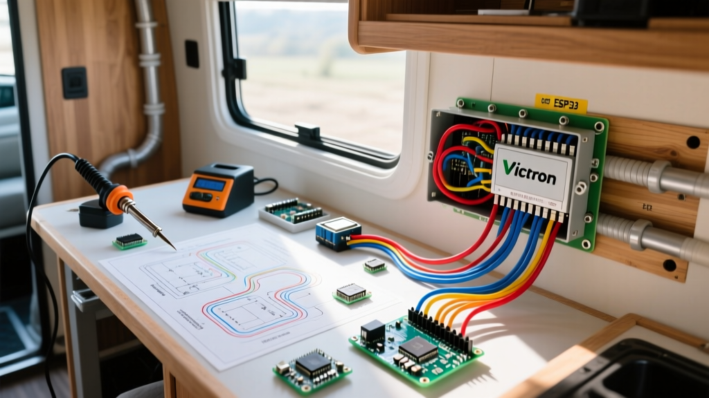
Where you mount your heavy electrical components dictates how you route your camper electrical wiring. The Victron Energy wiring guidelines emphasize that high-current devices generate significant heat.
If you are installing a Victron MultiPlus-II 12/3000/120-50 Inverter/Charger (approx. $1,650), it requires a minimum of 4 inches of clearance on the top and sides for internal fan ventilation. Mounting this unit inside a sealed bench seat without active ventilation louvers will cause it to thermally derate, cutting your AC output in half on hot summer days.
The Ideal Electrical Closet Layout
- Bottom Tier: LiFePO4 Battery Bank (e.g., Epoch 12V 230Ah Bluetooth). Keep as low as possible to lower the center of gravity.
- Mid Tier: Main DC Busbars, Class T Fuse, and Battery Monitor Shunt (Victron SmartShunt 500A).
- Upper Tier: Inverter/Charger and Solar Charge Controllers. Heat rises; keeping these at the top prevents them from baking the batteries below.
Common Renovation Wiring Failure Modes
Even with perfect schematics, physical installation errors cause the majority of camper electrical fires and system failures. Avoid these specific edge cases:
- Chafing on Sheet Metal: When routing wire through the metal ribs of a Ford Transit or Mercedes Sprinter, you must use rubber grommets or split loom tubing secured with adhesive-backed P-clips. Bare wire resting on bare metal will eventually vibrate through the insulation and cause a dead short.
- Poor Crimp Connections: Hand-crimping 2/0 AWG lugs with a hammer crimper often leaves micro-voids inside the lug barrel. This increases resistance, generating massive heat at the terminal. Invest in a hydraulic crimper (like the Knoweasy 16-Ton) and use adhesive-lined 3M EPS300 heat shrink to create a watertight seal.
- Undersized AC Transfer Switches: If wiring shore power, ensure your automatic transfer switch is rated for the full amperage of your shore inlet (typically 30A or 50A). Using a 20A switch on a 30A inlet will melt the contacts when running the AC and microwave simultaneously.
Step-by-Step Rough-In Sequence
To ensure a smooth renovation, follow this exact rough-in sequence before installing your interior wall paneling or insulation:
- Drill and Grommet: Drill all necessary pass-through holes in bulkheads and metal framing. Install rubber grommets immediately.
- Pull AC Lines: Run your 120V AC Romex from the shore power inlet to the breaker box, and from the breaker box to all AC outlets. Keep these lines bundled separately.
- Pull DC Trunk Lines: Run your heavy 2/0 AWG and 4 AWG wires from the planned battery location to the inverter and solar charge controller locations.
- Pull DC Branch Circuits: Run 12 AWG or 14 AWG marine wire to all 12V lights, fans, and USB receptacles.
- Label Everything: Use a thermal label maker to tag both ends of every single wire with its destination and fuse size (e.g., "MAXXFAN - 15A"). This single step will save you hours of troubleshooting when terminating connections weeks later.
By treating your camper electrical wiring as a centralized, meticulously planned network rather than an afterthought, you guarantee a safe, efficient, and resilient power system capable of handling the demands of modern off-grid living.