
The Quantum Reality of Insulator Electricity
When we discuss insulator electricity, we are fundamentally talking about the restriction of electron flow. In the realm of solid-state physics, the behavior of any material is dictated by its electronic band structure. Conductors have overlapping valence and conduction bands, allowing electrons to move freely. Insulators, however, possess a wide 'forbidden energy gap' (band gap) typically greater than 5 electron-volts (eV). This massive gap requires an extraordinary amount of energy—usually in the form of extreme heat or immense voltage—to excite an electron from the valence band into the conduction band.
For electrical engineers, DIYers, and wire sizing specialists, understanding insulator electricity is not just about preventing shocks. It is about managing dielectric stress, preventing partial discharge, and ensuring that the physical dimensions of your wiring meet National Electrical Code (NEC) conduit fill requirements. According to Georgia State University HyperPhysics, the macroscopic property we measure as 'dielectric strength' is the direct result of this quantum band gap resisting electrical avalanche breakdown.
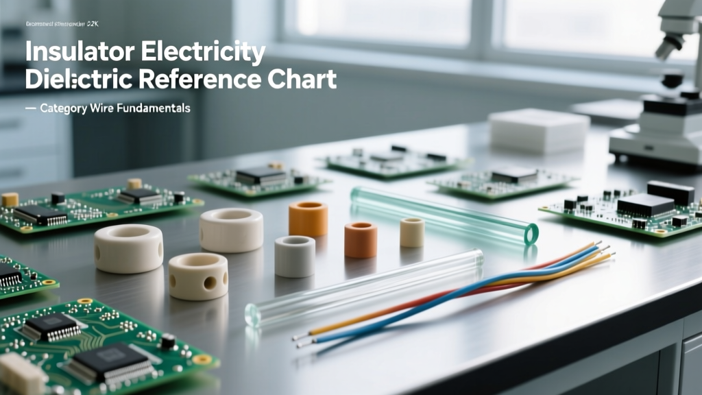
Quick Reference: Dielectric Strength & Material Chart
Dielectric strength is the maximum electric field that a pure material can withstand under ideal conditions without breaking down (i.e., without experiencing a failure of its insulating properties). It is typically measured in kilovolts per millimeter (kV/mm). Below is a quick-reference cheat sheet for the most common insulation materials used in residential, commercial, and industrial wiring.
| Insulation Material | Dielectric Strength (kV/mm) | Max Continuous Temp (°C) | Volume Resistivity (Ω·cm) | Primary Application |
|---|---|---|---|---|
| PVC (Polyvinyl Chloride) | 14 - 40 | 70°C - 105°C | >10^14 | Standard THHN/THWN building wire, appliance cords |
| XLPE (Cross-Linked Polyethylene) | 20 - 50 | 90°C - 150°C | >10^16 | High-voltage underground feeders, premium THHN |
| PTFE (Teflon) | 60 - 130 | 260°C | >10^18 | Aerospace wiring, high-frequency coaxial cables |
| Silicone Rubber | 15 - 30 | 180°C - 200°C | >10^15 | High-temp flexible leads, heating element wiring |
| Alumina Ceramic | 13 - 35 | 1700°C+ | >10^14 | High-voltage transmission line pin insulators |
Material Deep Dives: Choosing the Right Jacket
PVC: The Industry Workhorse
Polyvinyl Chloride dominates the residential and commercial wiring market due to its low cost, excellent flame retardancy (when formulated with plasticizers and stabilizers), and adequate dielectric strength. However, PVC has a high dielectric constant (around 3.5 to 4.0), which makes it unsuitable for high-frequency data cables due to signal attenuation and capacitance issues. Furthermore, standard PVC becomes brittle below freezing and softens dangerously above 70°C unless specifically cross-linked or heavily modified.
XLPE: The High-Voltage Champion
Cross-Linked Polyethylene (XLPE) is created by forming three-dimensional molecular bonds between polyethylene chains. This thermal and chemical transformation turns a thermoplastic into a thermoset material. As noted by the British Plastics Federation, XLPE's molecular network prevents the material from melting under extreme short-circuit temperatures (up to 250°C for short durations). Its low dielectric constant (~2.3) and exceptional volume resistivity make it the undisputed king of medium and high-voltage underground distribution cables.
PTFE (Teflon): The Aerospace Standard
PTFE relies on a dense shield of fluorine atoms surrounding a carbon backbone. This fluorine-carbon bond is one of the strongest in organic chemistry, granting PTFE its legendary chemical inertness and thermal stability. In insulator electricity applications, PTFE boasts the highest dielectric strength of common polymers and an incredibly low dissipation factor, making it mandatory for high-frequency RF applications, military avionics, and environments where outgassing could ruin sensitive optical or vacuum equipment.
Failure Modes: When Insulator Electricity Breaks Down
Insulation rarely fails instantly without warning. In real-world applications, the degradation of insulator electricity is a progressive failure mode. Understanding these mechanisms is critical for troubleshooting mysterious breaker trips, ground faults, and equipment damage.
1. Electrical Treeing and Water Trees
Particularly prevalent in underground XLPE and PVC cables, 'treeing' occurs when microscopic voids or impurities in the insulation experience localized high electric fields. Over years of AC voltage cycling, these fields initiate micro-discharges (partial discharges) that slowly carve microscopic, fern-like channels through the dielectric. 'Water trees' form when moisture is present, accelerating the degradation. Once an electrical tree bridges the gap between the conductor and the ground shield, catastrophic avalanche breakdown occurs, resulting in a dead short.
2. Surface Tracking and Creepage
Solid insulators can fail not through their bulk material, but across their surface. When dust, moisture, and ionic contaminants settle on an insulator (like a ceramic transmission line insulator or a PCB terminal block), a conductive path forms. Leakage current flows across this path, generating localized heat that dries the moisture, leading to micro-arcing. This arcing carbonizes the surface of the insulator. Since carbon is conductive, the tracking path grows until it bridges the terminals, causing a flashover. This is why high-voltage insulators feature deep 'sheds' or ribs—to artificially increase the creepage distance.
3. Thermal Degradation and Plasticizer Migration
When wires are subjected to temperatures near their maximum rating for extended periods, the chemical plasticizers in PVC begin to migrate and evaporate. The insulation loses its flexibility, becoming rigid and brittle. Any subsequent mechanical vibration or thermal expansion/contraction will cause micro-cracks in the jacket. According to UL Wire and Cable Testing Standards, thermal aging tests are critical because a cracked insulator exposes the bare conductor, instantly reducing the dielectric barrier to zero and creating a severe fire or shock hazard.
How Insulation Affects Wire Sizing & Conduit Fill
A common mistake among DIYers and junior electricians is confusing the conductor size (measured in AWG or circular mils) with the overall wire diameter. Insulator electricity dictates the thickness of the dielectric barrier required to safely contain the voltage. Higher voltages and higher temperatures require thicker or denser insulation layers.
Expert Sizing Rule: When calculating conduit fill per NEC Chapter 9, Table 1, you must use the overall cross-sectional area of the wire, including the insulation. A 10 AWG THHN wire with a thin nylon/PVC jacket takes up significantly less conduit space than a 10 AWG wire wrapped in thick silicone rubber for high-temperature applications.
Calculating the True Cross-Sectional Area
To accurately size your conduit, you must account for the insulation thickness. For example, a standard 12 AWG solid copper conductor has a bare diameter of roughly 0.0808 inches. However, when wrapped in THHN insulation (PVC base with a nylon skin), the overall diameter increases to approximately 0.115 inches.
- Bare Conductor Area (12 AWG): ~0.0051 sq inches
- Insulated THHN Area (12 AWG): ~0.0104 sq inches
The insulation effectively doubles the physical space the wire occupies in a raceway. If you ignore the insulator's physical footprint, you risk overfilling the conduit. Overfilled conduits prevent heat dissipation, leading to thermal runaway, which degrades the insulator electricity properties, lowers the dielectric strength, and ultimately causes a catastrophic insulation failure.
Summary Checklist for Material Selection
- Standard Indoor Branch Circuits: PVC/Nylon (THHN/THWN-2) is cost-effective and meets all NEC requirements for 600V systems.
- High-Temp Environments (Ovens, Kilns): Silicone Rubber or Fiberglass braided sleeves are mandatory to prevent thermal embrittlement.
- Underground High Voltage: XLPE is required for its resistance to water treeing and superior short-circuit thermal endurance.
- High-Frequency / RF Data: PTFE or Foamed PE to minimize dielectric losses and signal capacitance.
Mastering insulator electricity means looking beyond the copper or aluminum core. The dielectric jacket is the unsung hero of electrical safety, dictating not only the thermal and voltage limits of your circuit but also the physical geometry of your entire wiring infrastructure.