Beyond the Textbook: How We Define Alternating Current on the Job
When engineering textbooks define alternating current, they typically describe it as an electric charge that periodically reverses direction, contrasting it with direct current (DC). However, for electricians, electronics technicians, and advanced DIYers, this academic definition falls short. On the job site, to truly define alternating current means understanding its waveform, its Root Mean Square (RMS) heating potential, and its profound impact on wire sizing, breaker selection, and motor operation.
In this guide, we move past the basic physics of the War of the Currents and explore how AC behaves in modern residential panels, industrial motor circuits, and high-amperage feeder runs.
The Anatomy of an AC Waveform in Residential Panels
Alternating current in the North American power grid is delivered as a sinusoidal wave. The voltage starts at zero, rises to a positive peak, drops back through zero to a negative peak, and returns to zero. This entire sequence constitutes one cycle, repeating 60 times per second (60Hz).
Why Your Multimeter Reads 120V (The RMS Reality)
A common point of confusion for beginners is the difference between peak voltage and the voltage displayed on a digital multimeter (DMM). The peak voltage of a standard US residential receptacle is actually 169.7V. However, we define alternating current's effective voltage using Root Mean Square (RMS). RMS is the equivalent DC voltage that would produce the exact same heating effect in a resistive load. According to Fluke's electrical testing guidelines, True-RMS multimeters are essential for accurately measuring this heating potential, especially when dealing with non-linear loads like LED drivers or variable frequency drives (VFDs) that distort the sine wave.
| Metric | 120V Nominal Circuit | 240V Nominal Circuit |
|---|---|---|
| RMS Voltage (What DMM Reads) | 120V | 240V |
| Peak Voltage (Max Amplitude) | 169.7V | 339.4V |
| Peak-to-Peak Voltage | 339.4V | 678.8V |
Split-Phase Power: The North American 120/240V Standard
To properly define alternating current in a US residential context, you must understand split-phase power. The utility transformer outside your home features a center-tapped secondary winding. This creates two 120V 'legs' (L1 and L2) that are 180 degrees out of phase with one another, plus a grounded neutral conductor.
According to the NEC, identifying these AC legs correctly is critical for safety and maintenance. In a 120/240V split-phase system, L1 is typically insulated in black, L2 in red, and the neutral in white or gray. The equipment grounding conductor (EGC) must be bare copper or green. Misidentifying L2 as a neutral or using white tape on a black wire without properly marking it at both terminations can lead to catastrophic short circuits when a future DIYer assumes the wire is a grounded conductor.
Troubleshooting Leg Imbalances and Floating Neutrals
Because L1 and L2 are 180 degrees out of phase, the potential difference between them is 240V (used for dryers, ranges, and HVAC). The neutral wire only carries the unbalanced current between the two legs. If a multi-wire branch circuit (MWBC) loses its neutral connection—a dangerous failure mode known as a 'floating neutral'—the circuit becomes a series 240V loop. A 120V TV on L1 might receive 180V and fry its power supply, while a 120V lamp on L2 dims to a faint glow. This real-world scenario underscores why the NEC strictly requires simultaneous disconnection of all ungrounded conductors in an MWBC.
Frequency, Motors, and the 60Hz vs. 50Hz Divide
The frequency of AC power dictates the speed of induction motors. The synchronous speed of an AC motor is calculated by the formula: Speed = (120 × Frequency) / Number of Poles.
If you import a 50Hz European appliance or industrial pump to a 60Hz North American grid, the motor will attempt to run 20% faster. This increases the mechanical load, draws higher amperage, and often leads to premature thermal failure. Conversely, running a 60Hz motor on 50Hz power reduces cooling fan speed while increasing magnetic core saturation, causing rapid overheating. When wiring international equipment, you must use a VFD or a dedicated frequency converter, rather than just adapting the plug.
Harmonics, Power Factor, and Non-Linear Loads
In the 20th century, alternating current primarily powered resistive loads (incandescent heaters) and inductive loads (AC motors). Today, the proliferation of switch-mode power supplies (SMPS) in computers, LED lighting, and solar inverters has fundamentally changed how AC behaves in residential and commercial panels. These devices draw current in abrupt, high-amplitude pulses at the peak of the voltage waveform rather than smoothly following the sine wave.
This creates 'harmonics'—multiples of the fundamental 60Hz frequency (e.g., 180Hz, 300Hz). Triplen harmonics (3rd, 9th, 15th) do not cancel out on the neutral wire; they add up. In a commercial office building with hundreds of LED drivers and PCs, the neutral conductor can actually carry more current than the phase conductors. This is why modern electrical codes often require oversized neutral busbars and 200% rated neutral feeders in high-harmonic environments. Furthermore, this phase-shift between voltage and current creates a poor 'Power Factor', forcing utilities to supply more apparent power (kVA) than the actual real power (kW) consumed.
AC Wire Sizing: Skin Effect and Proximity Effect
When we define alternating current for wire sizing purposes, we must account for the 'Skin Effect.' Unlike DC, which utilizes the entire cross-sectional area of a conductor evenly, AC generates a magnetic field that forces electrons toward the outer surface (the 'skin') of the wire.
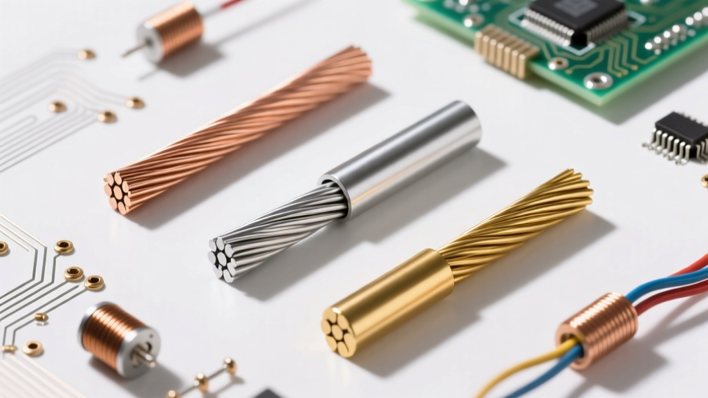
At standard 60Hz utility power, the skin effect is negligible for conductors smaller than 1/0 AWG. However, for massive 500 MCM or 750 MCM feeders used in commercial switchgear, the center of the copper carries almost no current. To combat this, electrical engineers and wire manufacturers use stranded conductors, and in high-frequency applications (like VFD output cables), specialized shielded, symmetrically grounded cables are required to prevent corona discharge and insulation breakdown. The National Electrical Code (NFPA 70) provides specific derating tables in Chapter 9 to account for these AC-specific impedance factors.
Practical Safety: Testing and Terminating Live AC
Working with AC requires specific diagnostic tools. Digital multimeters have high-impedance inputs, making them susceptible to 'phantom voltage'—capacitive coupling from adjacent live wires that can make a dead wire appear to have 40V to 90V on it.
To confidently define alternating current's presence or absence in a cable, professionals use low-impedance solenoid testers (often called 'Wiggys') or modern LoZ (Low Impedance) DMM modes. These tools draw a small amount of current, bleeding off phantom voltages and giving a definitive reading of actual, usable AC power.
Expert Safety Note: Never rely solely on a non-contact voltage tester (NCVT) to verify an AC circuit is de-energized before touching bare copper. NCVTs detect capacitive electric fields, which can yield false positives from static or false negatives if the tester's battery is low or the user's grip doesn't provide a proper ground reference. Always perform a live-dead-live test with a rated contact voltage tester.
Summary: The Working Definition of AC
To define alternating current in the field is to understand a dynamic, time-varying force. It is a 60Hz sine wave whose RMS value dictates thermal wire sizing, whose split-phase topology powers our heavy appliances, and whose skin effect influences how we terminate massive commercial feeders. Mastering these real-world characteristics separates the textbook student from the master electrician.