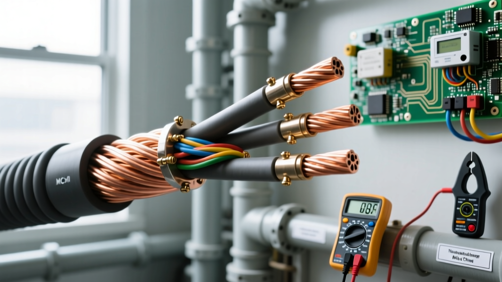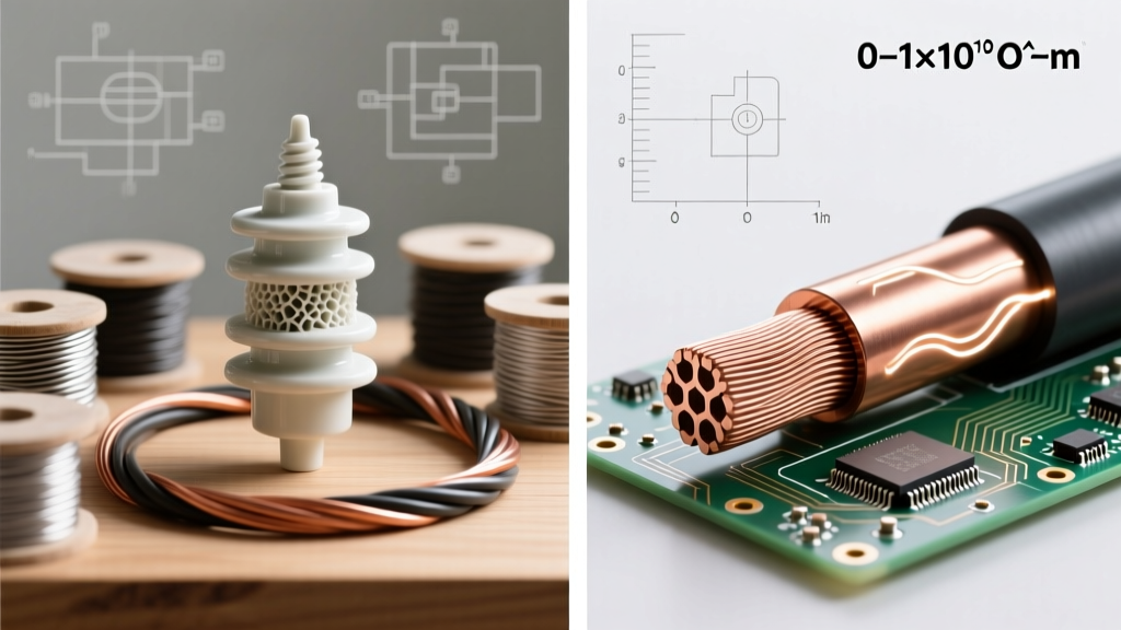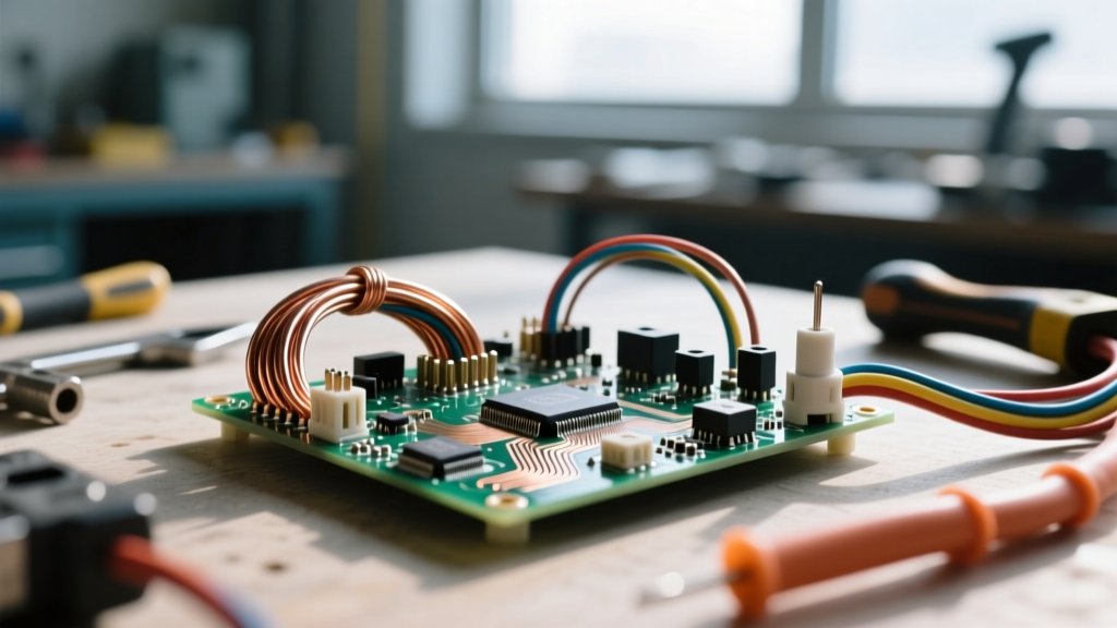

The Physics of Conductivity and Resistance
At the atomic level, the distinction between conductive and insulating materials comes down to electron mobility and band gaps. In electrical engineering and DIY wiring, understanding these properties is not just academic—it dictates how we size wires, manage heat, and prevent catastrophic short circuits. Conductors possess a 'sea of electrons' in their valence band that can move freely when a voltage potential is applied. Insulators, conversely, have tightly bound electrons and a massive band gap, requiring extreme voltage to force current flow (dielectric breakdown).
For electricians, makers, and engineers, selecting the right material means balancing conductivity, tensile strength, thermal limits, and environmental resistance. Below is a comprehensive quick-reference guide detailing practical examples of conductors and insulators used in modern electrical systems.
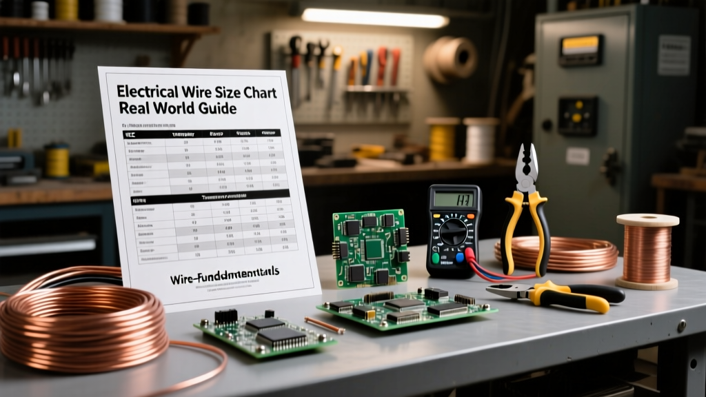
Master Quick-Reference Chart: Examples of Conductors and Insulators
The following table categorizes common materials by their primary electrical function, providing critical metrics for real-world applications. Conductivity is measured against the International Annealed Copper Standard (IACS), where pure annealed copper equals 100%.
| Material | Classification | Conductivity (% IACS) | Dielectric Strength (kV/mm) | Primary Application |
|---|---|---|---|---|
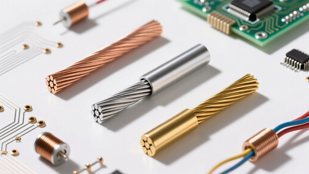
| Silver (Ag) | Conductor | 105% | N/A | RF contacts, aerospace relays, high-end audio |
| Copper (C11000) | Conductor | 101% | N/A | Standard building wire (THHN), PCB traces, busbars |
| Gold (Au) | Conductor | 70% | N/A | Corrosion-resistant edge connectors, IC bonding |
| Aluminum (AA-8000) | Conductor | 61% | N/A | Service entrance cables, heavy feeder wires, transmission |
| PVC (Polyvinyl Chloride) | Insulator | N/A | 15 - 40 | Standard wire jacketing (THHN), low-cost cordsets |
| XLPE (Cross-Linked PE) | Insulator | N/A | 20 - 30 | High-temp building wire (XHHW-2), medium voltage cables |
| PTFE (Teflon) | Insulator | N/A | 60 - 100 | Aerospace wiring, high-frequency coax, extreme heat zones |
| Mica | Insulator | N/A | 100 - 200 | High-voltage switchgear, heating element insulation |
| Air (Standard) | Insulator | N/A | ~3 | Clearance gaps, overhead transmission spacing |
Metallic Conductors: Alloys, Grades, and Field Realities
When evaluating examples of conductors, it is crucial to look beyond the base element and examine the specific alloy and temper. The Copper Development Association outlines dozens of copper alloys, but only a few dominate electrical wiring.
Copper: The Undisputed Standard
Electrolytic Tough Pitch (ETP) copper, designated as C11000, is the workhorse of the electrical industry. It offers 101% IACS conductivity and excellent ductility. For high-precision applications like vacuum electronics or high-end audio, Oxygen-Free High Thermal Conductivity (OFHC) copper (C10200) is used to prevent hydrogen embrittlement during high-temperature brazing. In DIY and residential wiring, solid C11000 copper is preferred for its reliable termination under standard brass or copper alloy lug screws.
Aluminum: The Feeder Alternative
Historically, pure aluminum (AA-1350) caused widespread failures in the 1970s due to thermal expansion and cold creep, leading to loose connections and fires. Modern aluminum building wire utilizes the AA-8000 series alloy, which incorporates iron and copper to stabilize the metal's creep characteristics. While aluminum only possesses about 61% of the conductivity of copper, its significantly lower density means a pound of aluminum can conduct nearly twice the current of a pound of copper. When using aluminum, technicians must apply anti-oxidant joint compound (like Noalox) and use terminals explicitly rated CO/ALR to prevent galvanic corrosion and high-resistance oxidation layers.
Dielectric Insulators: Polymers, Ceramics, and Thermal Limits
Insulators do more than just block current; they provide mechanical protection, chemical resistance, and thermal management. According to fundamental electrical theory covered by All About Circuits, an insulator's effectiveness is measured by its dielectric strength—the maximum electric field it can withstand before breaking down and becoming conductive.
PVC vs. XLPE in Building Wire
Polyvinyl Chloride (PVC) is the most ubiquitous insulator due to its low cost and flexibility. However, standard PVC begins to degrade and melt at temperatures exceeding 105°C. In modern commercial and residential wiring, Cross-Linked Polyethylene (XLPE) has largely replaced PVC for critical circuits. XLPE features a thermoset molecular structure that does not melt under high heat, allowing wires like XHHW-2 to safely operate at 90°C in wet or dry locations while withstanding severe short-circuit thermal spikes without deforming.
PTFE and High-Performance Polymers
For environments involving extreme heat, corrosive chemicals, or high-frequency RF signals, PTFE (Teflon) is the insulator of choice. PTFE boasts an incredibly low dielectric constant, minimizing signal loss in high-speed data cables and coaxial lines. Furthermore, its dielectric strength is exceptionally high, allowing for thinner insulation jackets in aerospace applications where weight reduction is paramount.
Environmental Degradation: When Insulators Fail
No insulator is perfect forever. Field failures rarely occur because the material was inherently flawed; they occur due to environmental degradation overcoming the material's dielectric limits.
- Water Treeing: In underground medium-voltage cables, microscopic impurities combined with moisture and electrical stress create dendritic 'water trees' within the XLPE insulation. Over years, these trees bridge the gap between the conductor and the ground shield, resulting in a catastrophic fault.
- Carbon Tracking: When dust, moisture, and salt accumulate on the surface of an insulator (like a ceramic standoff or a PCB), a leakage current can form. This current generates localized heat, carbonizing the organic contaminants. Carbon is conductive, creating a permanent low-resistance path across the insulator's surface, ultimately leading to a flashover.
- UV and Ozone Degradation: Standard PVC and rubber insulators break down when exposed to direct sunlight or high-ozone environments (such as near electric motors). The polymer chains fracture, leading to chalking, brittleness, and eventual cracking that exposes the live conductor.
Field Verification: Testing Insulation Integrity
Visual inspection is insufficient for verifying the health of an insulator. Electrical professionals rely on Insulation Resistance (IR) testing using a Megohmmeter (commonly referred to by the brand name Megger). As detailed in Fluke's testing guidelines, applying a high DC voltage (typically 500V or 1000V for low-voltage systems) stresses the insulation, allowing technicians to measure leakage current in megohms or gigohms.
Expert Troubleshooting Tip: A single spot reading on a megohmmeter can be misleading due to surface moisture or capacitive charging. Always calculate the Polarization Index (PI)—the ratio of the 10-minute IR reading to the 1-minute IR reading. A PI value below 1.0 indicates severe moisture ingress or contamination within the insulation matrix, even if the initial spot reading appeared acceptable.
Semiconductors: The Intentional Middle Ground
While this guide focuses on strict conductors and insulators, it is worth noting the role of semiconductors (like Silicon and Germanium). In power electronics, the insulating layers of silicon dioxide (SiO2) inside MOSFETs and IGBTs are microscopically thin. A gate voltage of just 20V can exceed the dielectric breakdown limit of these nano-scale insulators, permanently destroying the component. This highlights a critical rule in electronics: dielectric strength is a function of both the material's inherent chemistry and its physical thickness.
Summary for the Workbench
Whether you are pulling 4/0 AWG aluminum feeders through underground conduit or soldering 28 AWG silver-plated copper wire to a microcontroller, the fundamental physics remain unchanged. Conductors must be chosen for their ampacity, voltage drop characteristics, and termination compatibility. Insulators must be selected based on their thermal rating, dielectric strength, and environmental resilience. Keep this quick-reference guide handy to ensure your next wiring project is built on a foundation of sound material science.