
At-a-Glance: Core Definitions
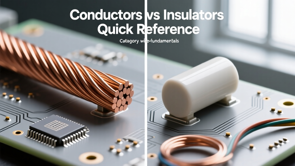
When designing circuits, selecting wire gauges, or troubleshooting a fault, understanding the fundamental difference between electrical conductors and insulators is non-negotiable. In practical terms: conductors facilitate the free flow of electrical charge (current), while insulators restrict it to safe, designated pathways. However, the boundary between these two material classes is not just a simple binary; it is defined by quantum mechanics, thermal dynamics, and voltage thresholds. This quick reference guide bypasses the fluff and delivers the hard data, material rankings, and failure modes every electrical professional and DIYer needs to make informed decisions on the bench or in the field.
The Atomic Reason: Energy Band Gap Theory
To truly grasp why copper conducts and PVC insulates, you must look at the atomic level—specifically, the Energy Band Gap. According to solid-state physics, electrons in a material occupy specific energy bands. The two most critical bands are the Valence Band (where electrons are bound to atoms) and the Conduction Band (where electrons are free to move and carry current).
- Conductors: The valence and conduction bands overlap. There is zero energy gap (0 eV). Electrons require virtually no external energy to break free and flow as current.
- Insulators: There is a massive energy gap (typically >5 eV) between the valence and conduction bands. Under normal voltages, electrons cannot bridge this gap, effectively halting current flow.
- Semiconductors: These sit in the middle with a small band gap (1-3 eV), allowing them to act as insulators at low temperatures and conductors when energized or heated.
For a deeper dive into the quantum mechanics of material conductivity, the HyperPhysics project at Georgia State University provides an excellent foundational breakdown of band theory.
Quick Reference Comparison Matrix
| Property | Conductors | Insulators |
|---|---|---|
| Band Gap | 0 eV (Overlapping bands) | >5 eV (Wide gap) |
| Primary Charge Carriers | Free Electrons (or Ions in electrolytes) | None (under normal operating voltages) |
| Resistivity Range | 10^-8 to 10^-6 Ω·m | 10^8 to 10^16 Ω·m |
| Temperature Coefficient | Positive (PTC) - Resistance rises with heat | Negative (NTC) - Resistance drops with heat |
| Primary Function | Transport electrical energy/signals | Confine energy, prevent short circuits, protect users |
Real-World Material Rankings & Specifications
Not all conductors are created equal, and insulation materials vary wildly based on thermal and environmental demands. Here is how the industry standards stack up.
Top-Tier Conductors in Wire Sizing
Conductivity is measured against the International Annealed Copper Standard (IACS), where pure annealed copper is set at 100% IACS.
- Silver (1.59 × 10^-8 Ω·m | ~105% IACS): The most conductive elemental metal. Rarely used in bulk wiring due to extreme cost and susceptibility to tarnishing (silver sulfide), but prevalent in high-end audio contacts and specialized RF aerospace applications.
- Copper (1.68 × 10^-8 Ω·m | 100% IACS): The undisputed king of electrical wiring. It offers the best balance of high conductivity, tensile strength, and solderability. Used in almost all residential (NM-B) and commercial (THHN) wiring.
- Gold (2.44 × 10^-8 Ω·m | ~70% IACS): Inferior conductivity to copper, but highly prized for its absolute resistance to oxidation. Used almost exclusively for micro-thin plating on PCB edge connectors and IC pins.
- Aluminum (2.82 × 10^-8 Ω·m | ~61% IACS): While it requires a larger gauge (roughly 2 AWG sizes up) to carry the same ampacity as copper, aluminum is 70% lighter. This makes it the mandatory choice for high-voltage overhead transmission lines and heavy service entrance feeders.
Standard Insulators in Cable Manufacturing
Insulators are rated by their Dielectric Strength (the maximum electric field they can withstand before breaking down, measured in kV/mm) and thermal limits.
- PVC (Polyvinyl Chloride): Dielectric strength ~40 kV/mm. The standard for everyday THHN/THWN wire. Rated for 75°C to 90°C. Cheap, flexible, and flame-retardant, but emits toxic halogen gas when burned.
- XLPE (Cross-Linked Polyethylene): Dielectric strength ~50 kV/mm. The superior choice for medium and high-voltage underground cables. The cross-linking process allows it to maintain structural integrity at higher temperatures (90°C continuous, 250°C short-circuit) without melting.
- PTFE (Teflon): Dielectric strength >60 kV/mm. Used in aerospace, military, and high-temperature industrial environments. Capable of withstanding continuous temperatures up to 260°C while maintaining exceptional chemical inertness.
Thermal Behavior: Opposing Temperature Coefficients
One of the most critical, yet frequently overlooked, differences between conductors and insulators is how they react to heat. This is vital for derating calculations in crowded conduit.
Conductors exhibit a Positive Temperature Coefficient (PTC). As a copper wire heats up due to I²R (I-squared-R) losses or ambient temperature, the atoms vibrate more violently. This increased lattice vibration scatters the free-flowing electrons, causing electrical resistance to increase. This is why a hot motor draws less current than a cold motor upon startup.
Insulators exhibit a Negative Temperature Coefficient (NTC). As an insulator heats up, thermal energy is transferred to the electrons in the valence band. In extreme heat, this thermal energy can be enough to excite electrons across the band gap into the conduction band. Consequently, as temperature rises, an insulator's resistance decreases, leading to increased leakage current and, eventually, thermal runaway.
Failure Modes: When Insulators Become Conductors
Insulators do not fail gracefully. When the voltage applied across an insulator exceeds its dielectric strength, it undergoes Dielectric Breakdown. The immense electrical field literally tears electrons from their atomic bonds, creating a temporary, highly conductive plasma channel. In solid dielectrics like wire insulation, this results in a permanent carbonized track—a dead short.
Common real-world failure mechanisms include:
- Electrical Treeing: Microscopic, branch-like conductive channels that grow inside XLPE insulation due to localized high-voltage stress and impurities. Over years, these 'trees' bridge the gap to the conductor, causing catastrophic underground cable faults.
- Surface Tracking (Creepage): When moisture, dust, and salt accumulate on the surface of an insulator (like a ceramic standoff or terminal block), they form a weakly conductive path. Leakage current flows across the surface, generating heat that carbonizes the insulator, eventually leading to a surface arc flash.
- Thermal Degradation: Overloading a 14 AWG copper wire beyond its 15A ampacity rating will heat the PVC insulation past its glass transition temperature, causing it to melt, brittle, and expose the live conductor.
NEC Code Note: The National Electrical Code (NFPA 70) strictly governs insulation selection. Per Article 310, conductors must be selected based on their insulation temperature rating (e.g., 60°C, 75°C, 90°C) and the specific environmental conditions of the installation, including wet locations and corrosive atmospheres.
Field Testing: Verifying Insulation Integrity
Because the difference between a conductor and an insulator can degrade over time due to moisture, heat, and mechanical stress, field technicians rely on Insulation Resistance (IR) testing. Using a Megohmmeter (Megger), a high DC voltage (typically 500V or 1000V) is applied between the conductor and ground.
According to testing standards outlined by diagnostic equipment manufacturers like Fluke, a healthy, newly installed wire should exhibit insulation resistance in the Gigaohm (GΩ) range. The absolute minimum acceptable threshold for most low-voltage systems is 1 Megohm (1 MΩ). If the reading drops below this, the insulator is compromised, absorbing moisture, or actively tracking, and the wire must be replaced before it becomes an unintended conductor.
Summary
Mastering the difference between electrical conductors and insulators goes far beyond basic textbook definitions. It requires an understanding of band gaps, thermal coefficients, and dielectric breakdown limits. Whether you are sizing a 500 kcmil aluminum feeder or troubleshooting a degraded control circuit, respecting the physical limits of your conductive and insulative materials is the cornerstone of safe, reliable electrical design.