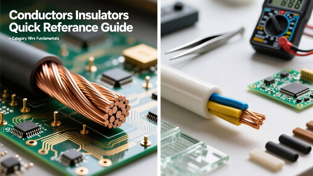

When electrical professionals and DIYers ask us to explain the difference between a conductor and an insulator, the most accurate answer begins at the atomic level before moving to macroscopic wire construction. While a basic definition states that conductors allow electron flow and insulators block it, true electrical mastery requires understanding band theory, dielectric breakdown thresholds, and thermal degradation limits. This quick-reference guide provides the hard data, material specifications, and field-testing insights necessary for safe and effective circuit design.
The Physics of Electron Flow: Band Theory
To truly understand material behavior, we must look at the energy bands of electrons. According to Georgia State University's HyperPhysics quantum models, electrons in a solid reside in specific energy levels grouped into bands. The two most critical bands are the valence band (the highest range of electron energies where electrons are normally present at absolute zero) and the conduction band (the range of electron energies higher than the valence band, where electrons are free to move and conduct electricity).
- Conductors: In materials like copper and silver, the valence band and the conduction band overlap. There is no "forbidden gap" (band gap). Because electrons require virtually zero additional energy to jump into the conduction band, they move freely through the atomic lattice when a voltage is applied.
- Insulators: In materials like cross-linked polyethylene (XLPE) or glass, there is a massive band gap—typically greater than 5 electron volts (eV)—separating the valence and conduction bands. Under normal operating voltages, electrons cannot bridge this gap, effectively halting current flow.
Quick Reference Comparison Matrix
The following table contrasts the fundamental electrical properties of common conductors and insulators used in modern wiring.
| Material Type | Specific Material | Electrical Resistivity (Ω·m at 20°C) | Band Gap (eV) | Primary Application |
|---|---|---|---|---|
| Conductor | Electrolytic Tough Pitch Copper (C11000) | 1.68 × 10⁻⁸ | Overlap (0) | Branch circuit wiring, busbars |
| Conductor | Aluminum Alloy (1350-H19) | 2.82 × 10⁻⁸ | Overlap (0) | Service entrance, transmission lines |
| Semiconductor | Silicon (for context) | 6.40 × 10² | 1.12 | Microcontrollers, solid-state relays |
| Insulator | Polyvinyl Chloride (PVC / THHN) | ~10¹⁴ to 10¹⁶ | > 6.0 | Standard indoor wire jacketing |
| Insulator | Cross-Linked Polyethylene (XLPE) | ~10¹⁶ to 10¹⁸ | > 8.0 | High-heat, wet locations (XHHW-2) |
Macroscopic Application: Wire and Cable Architecture
In practical wiring, conductors and insulators must work in perfect tandem. The conductor's job is to minimize voltage drop and heat generation (I²R losses), while the insulator's job is to contain the electromagnetic field and prevent fault currents.
Conductor Selection: Copper vs. Aluminum
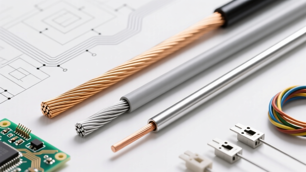
Copper remains the gold standard for residential and commercial branch circuits due to its low resistivity and high tensile strength. However, aluminum is frequently used for heavy feeders and service entrance cables. Because aluminum has roughly 61% of the conductivity of copper by volume, an aluminum conductor must be sized approximately two AWG sizes larger than its copper equivalent to carry the same ampacity safely. Furthermore, aluminum is prone to cold creep and oxidation, requiring the use of anti-oxidant compounds (like Noalox) and specific CO/ALR-rated terminations to prevent high-resistance connections that can lead to thermal fires.
Insulation Selection: PVC vs. XLPE
The National Electrical Manufacturers Association (NEMA) sets rigorous standards for wire insulation. The most common residential wire, THHN (Thermoplastic High Heat-resistant Nylon-coated), uses a PVC base. PVC is flexible and cost-effective but has a lower dielectric strength and thermal ceiling (typically rated for 90°C in dry locations). For harsher environments, XHHW-2 utilizes Cross-Linked Polyethylene (XLPE). The cross-linking process creates a three-dimensional molecular bond that prevents the insulation from melting under extreme heat, offering superior dielectric strength and resistance to environmental stress cracking.
Field Diagnostics: When Insulators Become Conductors
No insulator is perfect. If the applied voltage exceeds the material's dielectric strength (measured in kV/mm), the electric field will physically tear electrons from their atomic bonds, causing a catastrophic failure known as dielectric breakdown. This results in an arc flash or a dead short.
More commonly, insulators degrade slowly over time due to heat, moisture, and mechanical stress, gradually losing their high resistivity. Electrical troubleshooters use Insulation Resistance (IR) testing to catch this degradation before a failure occurs.
Pro-Tip for IR Testing: According to Fluke's insulation testing guidelines, you should never use a standard multimeter to test insulation. Multimeters typically output only 3 to 9 volts, which is insufficient to stress the dielectric material. Instead, use a Megohmmeter to apply high DC voltage (e.g., 500V DC for 600V-rated wire) to measure resistance in the megohm or gigohm range. A reading below 1 megohm indicates compromised insulation that requires immediate replacement.
The Polarization Index (PI)
For large motors and heavy feeders, a single IR reading isn't enough. Troubleshooters calculate the Polarization Index by dividing the 10-minute IR reading by the 1-minute IR reading. A PI ratio of less than 1.0 indicates dangerous moisture ingress or severe contamination, meaning the insulator is actively transitioning toward a conductive state.
Environmental Degradation and Thermal Limits
Temperature is the ultimate enemy of the insulator. As ambient heat increases, the thermal energy excites electrons within the insulating material, effectively narrowing the band gap and increasing leakage current. This is why the National Electrical Code (NEC) Article 310 strictly mandates ampacity derating based on temperature ratings.
For example, a 12 AWG THHN copper wire has an inherent insulation rating of 90°C, which might suggest it can handle 30 Amps. However, standard termination lugs on breakers and receptacles are typically rated for only 60°C or 75°C. Therefore, the NEC requires you to size the overcurrent protection based on the lowest temperature rating in the circuit chain, capping that 12 AWG wire at 20 Amps. Ignoring this interplay between the conductor's thermal limits and the insulator's degradation threshold is a primary cause of electrical fires in DIY projects.
Summary
Understanding the boundary between conduction and insulation is the foundation of electrical safety. Conductors are chosen for their overlapping energy bands and low resistivity, ensuring efficient power delivery. Insulators are chosen for their massive band gaps and high dielectric strength, ensuring that power stays exactly where it belongs. By respecting the thermal and environmental limits of both materials, you ensure long-lasting, code-compliant, and safe electrical installations.