
The Atomic Architecture of Electron Flow
Every electrical accident—from a minor static shock to a catastrophic arc flash—traces back to a fundamental failure in managing electron flow. To prevent these disasters, electrical professionals must deeply understand material properties at an atomic level. When safety engineers and master electricians define a conductor and insulator, they are not merely discussing abstract physics; they are establishing the physical boundaries between safe operation and lethal hazards. This safety guide explores the real-world behavior of these materials, how they degrade under stress, and how to protect yourself when the barrier fails.
Defining the Conductor: Intentional vs. Unintentional Paths
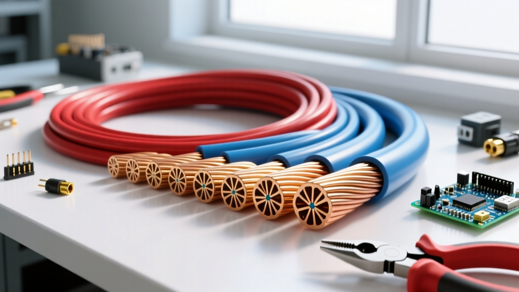
In physics, a conductor is defined as a material that permits the free flow of electrical charge. This is due to its atomic structure, specifically the presence of loosely bound valence electrons in its outer shell. Copper, the gold standard for branch circuit wiring, has a single valence electron that easily detaches and drifts when an electromotive force (voltage) is applied.
However, from a safety perspective, defining a conductor goes far beyond the copper or aluminum inside a cable jacket. An unintended conductor is any material that provides a rogue path to ground or between phases. Common unintended conductors include:
- The Human Body: Dry skin possesses a resistance of roughly 100,000 ohms, but broken, sweaty, or wet skin can drop this resistance to 1,000 ohms or less, making the body a highly efficient, lethal conductor.
- Impure Water: While pure H2O is an insulator, water with dissolved minerals, salts, or ions becomes a dangerous conductive medium, frequently causing ground faults in wet environments.
- Metal Chassis and Conduit: Equipment enclosures, EMT conduit, and structural steel act as massive, unintentional conductors if a bonding or grounding path fails.
The Dielectric Shield: How We Define an Insulator in Practice
An insulator is defined as a material with tightly bound electrons that strongly resist the flow of electrical current. In wiring, insulators (like PVC, XLPE, and Teflon) act as the dielectric shield, confining the current strictly to the intended conductive path.
However, a critical safety axiom is that no insulator is perfect. Every insulating material has a specific dielectric strength, measured in kilovolts per millimeter (kV/mm). This metric defines the exact voltage threshold required to rip electrons from their atomic bonds and force current through the material. When we define an insulator in the field, we must also define its operational limits regarding heat, UV exposure, and chemical degradation.
Material Matrix: Electrical Properties and Failure Modes
Understanding the specific ratings and vulnerabilities of common electrical materials is vital for hazard prevention. The table below outlines the baseline properties of standard conductors and insulators used in commercial and industrial wiring.
| Material | Role | Resistivity / Dielectric Strength | Common Safety Failure Mode |
|---|---|---|---|
| Copper (Cu) | Conductor | 1.68 × 10⁻⁸ Ω·m | Thermal creep at terminations, oxidation in damp environments |
| Aluminum (Al) | Conductor | 2.82 × 10⁻⁸ Ω·m | Galvanic corrosion when mated with copper, high thermal expansion |
| PVC (Polyvinyl Chloride) | Insulator | ~40 kV/mm | Embrittlement from UV, melting at 105°C, toxic smoke during fires |
| XLPE (Cross-linked PE) | Insulator | ~50 kV/mm | Water treeing in underground medium-voltage applications |
| EPDM Rubber | Insulator | ~30 kV/mm | Ozone cracking, mechanical tearing during cable pulling |
The Lethal Crossover: Dielectric Breakdown and Thermal Degradation
The most dangerous moment in any electrical system is when an insulator is pushed past its physical limits and begins to act as a conductor. This phenomenon is known as dielectric breakdown. In solid dielectrics like wire insulation, this usually results in a puncture or carbon tracking, creating a permanent, low-resistance fault path.
Thermal Runaway and Insulation Melting
Heat is the primary enemy of insulation. According to the NFPA 70E Standard for Electrical Safety in the Workplace, managing thermal limits is a core component of preventing arc flashes. Consider the difference between common wire insulations:
- THHN/THWN-2: Rated for 90°C in dry locations, but its rating drops to 75°C in wet environments. If installed in a damp conduit and subjected to continuous 90°C heat, the PVC jacket will degrade, plasticizers will leach out, and the insulation will become brittle and crack.
- XHHW-2: Utilizes XLPE insulation, maintaining its 90°C rating in both wet and dry locations. It also boasts a higher short-circuit temperature rating (250°C vs 150°C for THHN), meaning it can survive the intense thermal spike of a fault condition long enough for the breaker to trip without melting and exposing the live conductor.
When overcurrent protection devices (OCPDs) fail or are improperly sized, I²R heating cooks the wire from the inside out. The insulation melts, exposing the bare conductor, which inevitably leads to a phase-to-phase short or a phase-to-ground arc flash.
Field Safety Protocols: Verifying the Insulation Barrier
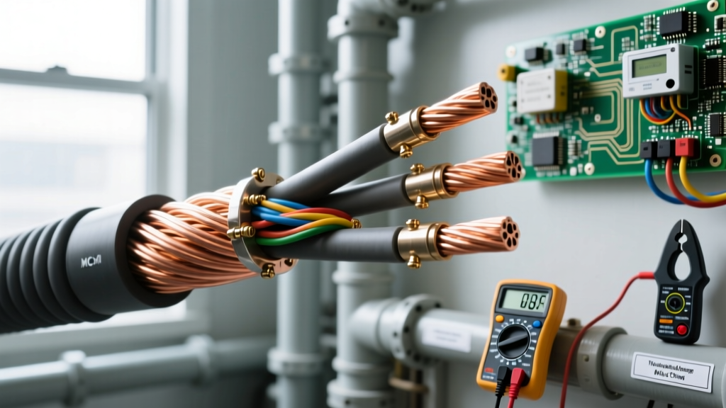
You cannot assume an insulator is intact simply by looking at it. Micro-fractures, moisture ingress, and internal carbon tracking are invisible to the naked eye. To ensure safety, electrical technicians must rely on empirical testing.
Insulation Resistance (IR) Testing
Following the IEEE 43 Recommended Practice for Testing Insulation Resistance, technicians use a Megohmmeter (commonly called a "Megger") to stress-test the dielectric barrier. By applying a high-voltage DC potential (e.g., 500V or 1000V) to the conductor and measuring the leakage current through the insulation to ground, technicians can calculate the resistance in Megohms (MΩ).
Safety Rule of Thumb: For low-voltage motors and wiring, a baseline insulation resistance of less than 1 MΩ indicates compromised insulation. The equipment must be locked out and tagged out (LOTO) immediately, as the risk of a ground fault or lethal shock is imminent.
Establishing Boundaries: When the Insulator is Removed
During maintenance, troubleshooting, or termination work, the insulating barrier is often removed, leaving bare, energized conductors exposed. At this point, safety relies entirely on establishing strict approach boundaries and utilizing personal protective equipment (PPE) to act as a secondary, wearable insulator.
Per OSHA Electrical Safety Standards and NFPA 70E, workers must observe the following boundaries:
- Limited Approach Boundary: The distance within which a shock hazard exists. Only qualified persons may cross this line.
- Restricted Approach Boundary: An increased risk of shock due to arc-over. Crossing this boundary requires insulated gloves, insulated tools, and a detailed energized work permit.
- Arc Flash Boundary: The distance at which incident energy equals 1.2 cal/cm² (the threshold for a second-degree burn). Appropriate arc-rated (AR) clothing must be worn within this zone.
When handling exposed conductors, voltage-rated rubber insulating gloves are mandatory. These are classified by maximum use voltage, ranging from Class 00 (rated for 500V AC) up to Class 4 (rated for 36,000V AC). Leather protectors must always be worn over the rubber gloves to prevent mechanical punctures that would compromise the dielectric shield.
Conclusion: Respecting the Boundary
To properly define a conductor and insulator in the context of electrical safety is to understand the fragile balance of energy containment. Conductors are the veins of our electrical infrastructure, but insulators are the immune system, keeping that energy contained and harmless. By respecting thermal limits, conducting rigorous dielectric testing, and adhering to strict approach boundaries, electrical professionals ensure that the barrier between safe operation and catastrophic failure remains unbroken.