
The 60-Second Verdict: Is Your Potentiometer Wired Correctly?
Wiring a potentiometer to a Variable Frequency Drive (VFD), DC motor controller, or custom HVAC control board seems straightforward: connect the reference voltage, ground, and wiper. But when you power up and the motor immediately jumps to 100% speed, or the dial feels completely backwards, the issue is almost always a pinout mismatch or a tapered track error. You cannot rely on silkscreen labels alone; manufacturer pinouts for 10kΩ control pots vary wildly between brands like Bourns, ALPS, and TT Electronics.
The only way to guarantee your wiring is correct before applying power to sensitive control logic is to perform a three-point resistance sweep with a multimeter. This guide gives you the exact meter setup, probe placements, and numerical thresholds to verify your connections, along with a decision tree to diagnose non-linear dead spots.
Meter Setup and Probe Placement for 3-Terminal Pots
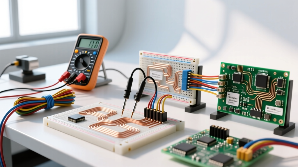
To accurately measure the resistive track and the wiper position, your multimeter must be configured to eliminate lead resistance and parallel circuit interference. According to Fluke's safety and measurement guidelines, ensuring your meter is set to the correct range prevents the internal battery from biasing sensitive semiconductor junctions if you accidentally probe a connected transistor base.
Meter Configuration Block
- Dial Position: Resistance (Ω). If your meter has manual ranging, select the 20kΩ range for a standard 10kΩ potentiometer.
- Lead Jacks: Black lead in COM, Red lead in V/Ω. (Do not use the mA/A jacks, or you will blow the meter's internal fuse).
- Zeroing: Touch the probes together. Note the lead resistance (usually 0.1Ω to 0.4Ω). Subtract this from your final readings if you are using a manual-range meter without a relative (REL) mode.
Probe Placement Strategy
Standard industrial potentiometers have three terminals. We will label them based on physical position when the shaft is facing you, but you must verify electrically:
- Test Point A (Left Terminal): Place the black probe here. This is typically the Counter-Clockwise (CCW) stop or Ground.
- Test Point B (Center Terminal): Place the red probe here. This is the Wiper (the variable output signal).
- Test Point C (Right Terminal): This is typically the Clockwise (CW) stop or Voltage Reference (Vref).
Expected Readings: Good vs. Bad Wiring Matrix
Assuming you are using a standard 10kΩ Linear (B-Taper) potentiometer—the universal standard for industrial motor speed references—here is exactly what your meter should display. If your readings deviate from the 'Good' column, your wiring is swapped or the component is defective.
| Probe Placement | Shaft Position | Expected Reading (Good) | Misleading/Bad Reading | Root Cause of Bad Reading |
|---|---|---|---|---|
| Left (A) to Right (C) | Any position | 9.8kΩ - 10.2kΩ | OL (Open) or 0.0Ω | Resistive track is snapped or shorted internally. |
| Left (A) to Wiper (B) | 50% rotation | 4.8kΩ - 5.2kΩ | ~1.5kΩ or ~8.5kΩ | Wrong taper (Audio/Log pot used instead of Linear). |
| Wiper (B) to Right (C) | 50% rotation | 4.8kΩ - 5.2kΩ | Fluctuating numbers | Dirty carbon track or oxidized wiper contact. |
| Left (A) to Wiper (B) | Full CCW (0%) | 0.0Ω - 0.5Ω | 10.0kΩ | Pins 1 and 3 are swapped in the wiring harness. |
Mistakes That Give Misleading Readings
The most common error DIYers make when wiring a potentiometer is assuming the physical layout of the pins dictates the electrical layout. On a Bourns 3590S series, Pin 1 is CCW. On some generic imported carbon pots, the wiper is on the left. Always trust the meter, not the silkscreen.
Another major source of misleading data is body resistance interference. If you hold the metal shaft of the potentiometer with your bare hand while probing the terminals, your body's resistance (roughly 50kΩ to 100kΩ depending on skin moisture) will parallel the circuit, pulling a 10kΩ reading down to 8.5kΩ. Hold only the insulated body of the probes and the plastic/metal mounting nut.
Decision Tree: Troubleshooting Non-Linear or Dead Spots
When the physical dial movement does not match the expected machine response, use this decision matrix to isolate the fault. This path terminates in a concrete hardware or wiring fix.
| Observed Symptom | Meter Test Result | Diagnosis | Concrete Fix / Action |
|---|---|---|---|
| Motor runs at 100% speed when dial is at 10%. | A-B reads 9kΩ at 10% rotation; B-C reads 1kΩ. | Reverse scaling. CW and CCW reference wires are swapped. | Swap the wires on Terminal A and Terminal C at the VFD block. |
| Motor speed stays at 0% for the first 70% of the dial turn, then spikes. | A-B reads 0.5kΩ at 50% rotation, then jumps to 8kΩ at 80%. | Wrong taper. An Audio (Logarithmic/A-Taper) pot was installed. | Replace with a Linear (B-Taper) pot. Pick: Bourns 3590S-1-103L. |
| Motor speed stutters or drops out completely at specific dial positions. | Meter display flashes 'OL' or jumps erratically during a slow sweep. | Wiper dead-spot. Carbon track is worn or contaminated with metal dust. | Clean with DeoxIT D5, or upgrade to a wirewound pot for high-reliability. |
| Dial feels loose, speed changes without touching the knob. | Resistance drifts by ±500Ω while the shaft is held perfectly still. | Wiper tension spring has fatigued; mechanical failure. | Replace the unit. Do not attempt to bend the wiper arm back into tension. |
Selecting the Right Replacement: Wirewound vs. Carbon Track
If your testing confirms the potentiometer is defective or the wrong taper, you need to select a replacement that matches the environmental and electrical demands of a control panel. According to the Bourns 3590 series technical datasheet, the construction material of the resistive track fundamentally changes how the component handles electrical noise and physical wear.
Carbon Composition (e.g., Alpha RV16AF)
Carbon pots are cheap ($2 to $4) and offer infinite resolution because the wiper slides over a solid carbon coating. However, they are highly susceptible to humidity, oxidize over time, and develop 'dead spots' that cause VFDs to trip on under-voltage faults. Use these only for low-stakes applications like audio equipment or simple LED dimmers.
Wirewound Precision (e.g., Bourns 3590S Series)
Wirewound pots use a physical wire wrapped around a core. The wiper moves from coil to coil. They cost more ($14 to $18 in 2026) but offer extreme durability, high power dissipation (up to 2W), and total resistance stability across temperature swings. The resolution is technically 'stepped' (roughly 100 to 200 steps per turn), but modern VFD analog inputs filter this out completely.