
The Hidden Cost of Incorrect Wires for Soldering in Industry
In consumer electronics, a failed solder joint might mean a returned gadget. In industrial automation, aerospace, or heavy machinery, a failed joint due to poor wire selection can result in catastrophic downtime, 480V short circuits, or total system loss. When procurement engineers and master technicians evaluate wires for soldering in high-stress environments, the focus must shift from basic conductivity to thermal shock resistance, vibration tolerance, and chemical stability.
As of 2026, the push toward higher-density motor control panels and miniaturized industrial IoT (IIoT) sensors means wires are often routed tighter and subjected to higher ambient heat. Selecting the correct wire requires a deep understanding of core metallurgy, insulation polymers, and stranding geometry. This guide breaks down the exact specifications required for industrial-grade soldering.
Core Metallurgy: Beyond Standard Bare Copper
While bare copper (ASTM B3) is the default for commercial wiring, it oxidizes rapidly in high-humidity industrial environments, leading to cold joints and increased electrical resistance. For industrial soldering, plated conductors are mandatory.
Silver-Plated Copper (ASTM B298)
Silver-plated copper (SPC) is the gold standard for aerospace and defense applications. The silver plating (typically 1-2 oz/ft²) prevents base copper oxidation and actually alloys with the tin in your solder, creating a metallurgical bond that is incredibly robust. SPC wires solder beautifully at standard 350°C iron temperatures. Expect to pay around $0.45 per foot for 18 AWG SPC wire in bulk.
Nickel-Plated Copper (ASTM B355)
When your application involves continuous ambient temperatures above 150°C (such as wiring inside industrial ovens or near exhaust manifolds), nickel-plated copper (NPC) is required. Nickel acts as a high-temperature diffusion barrier. However, NPC is notoriously difficult to solder. It requires higher iron tip temperatures (380°C - 400°C) and an aggressive, mildly activated rosin flux like Kester 186 or a specialized no-clean paste like Amtech NC-559-V2-TF to break the nickel oxide layer before the solder wets.
Insulation Selection: Surviving Thermal Shock
The most common failure mode when hand-soldering industrial wire is insulation melt-back. If the insulation shrinks or melts away from the solder joint, it exposes bare conductor, creating a severe short-circuit hazard in ungrounded metal chassis. According to Underwriters Laboratories (UL) safety frameworks, maintaining dielectric integrity right up to the solder fillet is critical for passing industrial safety audits.
PTFE (Teflon) and ETFE (Tefzel)
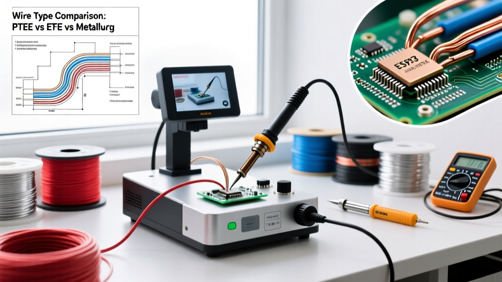
Polytetrafluoroethylene (PTFE) is the premier insulation for industrial soldering. It withstands continuous temperatures of 260°C and is virtually immune to melt-back from a soldering iron. MIL-W-22759/16 is the standard specification for extruded PTFE wire. Cross-linked ETFE (Tefzel), governed by MIL-W-22759/32, offers slightly lower heat resistance (150°C continuous) but provides vastly superior abrasion resistance, making it ideal for robotic arm articulation zones.
Silicone and Fiberglass
High-temperature silicone/fiberglass wires are common in heating element wiring. While the insulation won't melt, the braided fiberglass acts like a sponge, wicking liquid flux deep under the insulation jacket. Over time, trapped flux can corrode the wire. If using fiberglass wires, you must use no-clean flux sparingly and seal the termination with adhesive-lined heat shrink tubing.
Industrial Wire Insulation Comparison Matrix
| Insulation Material | Max Continuous Temp | Melt-Back Resistance | Solderability Rating | Primary Industry Application |
|---|---|---|---|---|
| PVC (Polyvinyl Chloride) | 105°C | Poor | Excellent | Consumer, Low-stress Panel Wiring |
| XLPE (Cross-linked PE) | 125°C | Fair | Very Good | Automotive, General Automation |
| ETFE (Tefzel) | 150°C | Very Good | Excellent | Robotics, CNC Machinery |
| PTFE (Teflon) | 260°C | Exceptional | Excellent | Aerospace, High-Density IIoT |
| Kapton (Polyimide) | 200°C | Exceptional | Good (Moisture Sensitive) | Space, Tight-Radius Avionics |
| Silicone/Fiberglass | 200°C - 450°C | Exceptional | Poor (Flux Wicking) | Industrial Heating, Foundries |
Stranding Configurations for Vibration and Flexing
Industrial environments are defined by vibration. Solid core wire will quickly work-harden and snap when subjected to the constant harmonic vibration of heavy 3-phase motors. Therefore, stranded wire is mandatory. However, not all stranding is equal when it comes to soldering.
Concentric Lay vs. Rope Lay (Bunched)
Concentric lay stranding is standard for static panel wiring. But for continuous flexing applications—such as cables routed through CNC drag chains—you must use rope-lay (bunched) stranding. Rope-lay wires group tiny strands into bundles, which are then twisted together, offering maximum flexibility.
Critical Soldering Warning for Flex Cables: When soldering rope-lay wires to terminal blocks, solder will naturally wick up into the stranding via capillary action. If solder wicks into the flex zone of the cable, it creates a rigid stress riser. Under continuous motion, the wire will snap exactly at the boundary where the flexible wire meets the solder-wicked stiff section. Always limit solder penetration to less than 50% of the terminal depth, and use mechanical strain relief.
Automated Soldering vs. Hand Soldering Wire Prep
In high-volume industrial manufacturing, the method of soldering dictates the wire preparation. According to IPC J-STD-001 standards for soldered electrical assemblies, wire prep must not damage the base conductor.
- Hand Soldering: Thermal wire strippers are highly recommended for PTFE and Kapton wires. Mechanical strippers often nick the silver or nickel plating, exposing the copper core to galvanic corrosion. A clean, nick-free strip of exactly 3mm for 22 AWG wire ensures consistent solder fillets.
- Automated Selective Soldering: If the wire will pass through a wave or selective soldering machine, the insulation must withstand 270°C+ bath temperatures for up to 3 seconds. PVC will melt and contaminate the solder dross. Only PTFE, ETFE, or high-temp Polyamide (PA) should be used for automated through-hole processes.
Troubleshooting Common Industrial Soldering Failures
Even with the correct wires for soldering, process errors can lead to field failures. Here are the most common edge cases encountered in industrial maintenance:
1. Tin Whisker Growth on Silver-Plated Wire
In high-humidity, low-voltage sensor circuits (e.g., 4-20mA RTD loops), the tin from the solder can migrate along the silver plating, forming conductive 'tin whiskers' that cause micro-shorts. Solution: Use a leaded solder alloy (Sn63/Pb37) where permitted by RoHS exemptions for critical industrial infrastructure, or apply a conformal coating (e.g., Humiseal 1B31) over the termination to physically suppress whisker growth.
2. Cold Joints on High-Mass Nickel Wire
When soldering 12 AWG or 10 AWG nickel-plated copper to heavy copper busbars, standard 40W irons cannot overcome the thermal mass. The flux burns off before the wire reaches flow temperature, resulting in a grainy, disturbed cold joint. Solution: Use a high-wattage soldering station (120W+) with a heavy chisel tip, pre-heating the busbar with a hot air gun set to 150°C to reduce the thermal delta.
Procurement Checklist for 2026 Builds
Before signing off on a BOM (Bill of Materials) for industrial control panels, verify your wire selections against this checklist:
- Verify Plating: Ensure bare copper is replaced with SPC or NPC for any environment exceeding 60% RH.
- Check Insulation Melt Point: Confirm insulation melting point is at least 100°C higher than your maximum soldering tip temperature.
- Match Stranding to Motion: Specify rope-lay stranding exclusively for drag-chain and robotic applications.
- Validate Flux Compatibility: Ensure your chosen flux chemistry (Rosin, No-Clean, or Water-Soluble) is compatible with the wire's insulation to prevent chemical degradation or wicking.
By treating wire selection as a critical metallurgical and polymer science decision rather than an afterthought, engineering teams can drastically reduce field failures and ensure long-term reliability in demanding industrial applications. For further reading on termination reliability, review the engineering whitepapers provided by TE Connectivity regarding high-vibration terminal block interfaces.