
When makers discuss Raspberry Pi 4 pinouts, the conversation usually stops at physical wiring diagrams. However, the 40-pin header is a highly multiplexed, software-defined interface. A physical pin might default to a 3.3V power source, a GPIO input with a pull-up resistor, or an alternate I2C bus, depending entirely on the operating system's Device Tree and your CLI configurations.
In this software walkthrough, we will bypass generic wiring charts and explore how to query, map, and manipulate Raspberry Pi 4 pinouts using terminal tools, Python scripts, and Device Tree overlays. Whether you are running Raspberry Pi OS Bullseye or the newer Bookworm release, mastering the software side of the GPIO header is critical for preventing hardware conflicts and diagnosing elusive bus errors.
The CLI Approach: Querying Pinouts Live via Terminal
Before writing a single line of Python or connecting a sensitive sensor, you should verify the current state of your target pins. The Raspberry Pi firmware provides a powerful, low-level utility called raspi-gpio for this exact purpose.
Open your terminal and query the state of BCM GPIO 2 (Physical Pin 3), which is typically used for I2C SDA:
raspi-gpio get 2The terminal will return a detailed string:
GPIO 2: level=1 fsel=0 func=INPUT pull=UPDecoding the Output
- level=1: The pin is currently reading HIGH (3.3V).
- fsel=0 / func=INPUT: The pin is configured as an input.
- pull=UP: The internal 50kΩ pull-up resistor is engaged. This is mandatory for I2C communication. If a software script accidentally sets this to
pull=DOWN, your I2C bus will hang, and hardware troubleshooting will yield no clues.
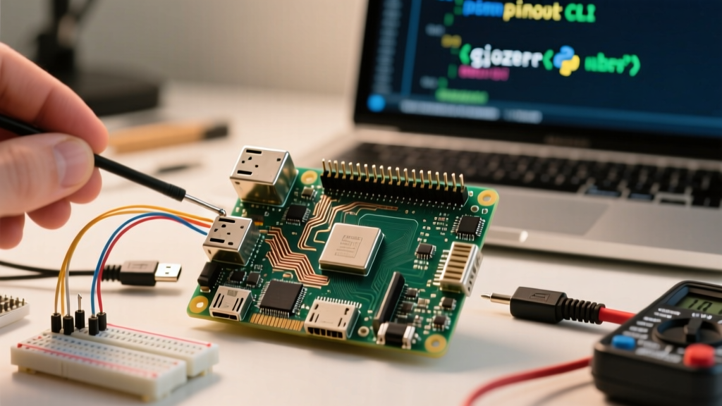
To view a visual map of the entire header directly in your terminal, ensure the gpiozero Python library is installed and run the pinout command. This outputs a color-coded ASCII diagram of the Raspberry Pi 4 pinouts, distinguishing between power, ground, and BCM-numbered GPIOs.
Software-Defined Pin Functions: A Reference Matrix
Physical pin numbers (1-40) are useless for software development. The Broadcom (BCM) numbering system is what the Linux kernel and Python libraries actually use. Below is a matrix of critical pins, highlighting their default software states and alternate functions.
| Physical Pin | BCM GPIO | Default Pull State | Primary Software Function | Alt Function / Notes |
|---|---|---|---|---|
| 3 | 2 | UP | I2C1 SDA | Requires i2c-dev kernel module |
| 5 | 3 | UP | I2C1 SCL | Used for HAT EEPROM detection on boot |
| 8 | 14 | NONE | UART TXD | Maps to /dev/ttyS0 (Mini UART) by default |
| 10 | 15 | NONE | UART RXD | Disable Bluetooth to map to PL011 UART |
| 19 | 10 | DOWN | SPI0 MOSI | Requires dtparam=spi=on |
| 21 | 9 | DOWN | SPI0 MISO | Shared with SPI0 bus |
| 27 | 0 | UP | I2C0 SDA | Reserved for HAT ID, avoid for general use |
| 29 | 5 | UP | GPIO 5 | General purpose, safe for interrupts |
Automating Pin Verification with Python gpiozero
When integrating complex hardware like relay boards or multiplexers, floating pins can cause erratic boot behavior. We can write a diagnostic Python script using the GPIO Zero Documentation library to sweep the GPIO header and detect unexpected shorts or floating states before applying main power to external peripherals.
from gpiozero import InputDevice
from time import sleep

# Define a list of BCM pins to test
target_pins = [17, 27, 22, 5, 6, 13, 19, 26]

print("Starting Pinout Diagnostic Sweep...")
for bcm in target_pins:
    # Initialize pin with internal pull-down
    pin = InputDevice(bcm, pull_up=False)
    sleep(0.05) # Allow voltage to settle

    if pin.is_active:
        print(f"[WARNING] BCM {bcm} is HIGH. Possible short to 3.3V!")
    else:
        print(f"[OK] BCM {bcm} is LOW (Floating/Pulled Down).")

    pin.close() # Release pin back to OS
Expert Warning: Software configuration cannot protect you from hardware voltage mismatches. The Raspberry Pi 4 GPIO operates strictly at 3.3V logic. Feeding a 5V signal into BCM 17 (Physical Pin 11) will permanently destroy the SoC's GPIO pad, regardless of how you configure the software pull resistors. Always use logic level shifters for 5V I2C or SPI devices.
Advanced Pin Mapping: Device Tree Overlays
The true power of the Raspberry Pi 4 pinout lies in its ability to be remapped via the Device Tree. Suppose your PCB design routed I2C to non-standard pins (e.g., BCM 23 and BCM 24) because the default hardware I2C pins were already in use. You do not need to redesign the board; you can create a software-defined I2C bus.
Creating a Bit-Banged I2C Bus
By editing your configuration file, you can instruct the Linux kernel to use CPU bit-banging to simulate an I2C bus on any available GPIO pins. Add the following line to your config:
dtoverlay=i2c-gpio,bus=3,i2c_gpio_sda=23,i2c_gpio_scl=24Upon reboot, the OS will generate a new device node at /dev/i2c-3. You can verify this mapping by running i2cdetect -y 3 in the terminal. This technique is invaluable for Home Assistant setups running multiple I2C environmental sensors that exceed the capacitance limits of the primary hardware bus.
Resolving UART and Serial Console Conflicts
A frequent point of failure when working with Raspberry Pi 4 pinouts is the UART interface on Physical Pins 8 and 10 (BCM 14 and 15). Out of the box, the Raspberry Pi maps these pins to the "Mini UART" (/dev/ttyS0), which is tied to the GPU core clock. If the CPU throttles under load, the core clock shifts, altering the UART baud rate and causing corrupted data packets with devices like GPS modules or Zigbee coordinators.
The Software Fix: Reclaiming the PL011 UART
To fix this, you must disable the Bluetooth module (which uses the stable PL011 UART by default) and remap the PL011 to the GPIO header. According to the Raspberry Pi Config.txt Documentation, add these lines:
enable_uart=1
dtoverlay=disable-bt
This forces the system to route the hardware-stable PL011 UART (/dev/ttyAMA0) to BCM 14 and 15, ensuring rock-solid serial communication regardless of CPU thermal throttling.
A Note on Raspberry Pi OS Bookworm Paths
If you are using the latest Debian Bookworm-based Raspberry Pi OS, the boot partition mount point has changed. You will no longer find the configuration file at /boot/config.txt. Instead, you must edit /boot/firmware/config.txt to apply your Device Tree overlays and UART remapping. Failing to recognize this path change is the number one reason software pinout configurations fail on modern Pi 4 deployments.
Conclusion
Mastering Raspberry Pi 4 pinouts requires looking beyond the physical silk-screen on the PCB. By leveraging raspi-gpio for live state querying, utilizing Python for automated continuity sweeps, and manipulating Device Tree overlays for custom bus routing, you transform the 40-pin header from a static breakout board into a dynamic, software-defined I/O matrix. For an exhaustive visual reference of alternate pin functions, always keep Pinout.xyz bookmarked in your development environment.