
Commercial off-the-shelf (COTS) smart home sensors often suffer from proprietary hub lock-in, rapid battery drain, and WiFi network congestion. For advanced home automation enthusiasts, building bespoke nodes using a Raspberry Pi and breadboard setup offers unparalleled flexibility. By leveraging the Pi's 40-pin GPIO header, you can rapidly prototype I2C sensor arrays and relay-driven actuators, ultimately hardwiring them into Home Assistant via MQTT. This guide dives deep into the electrical realities, specific component selections, and software architectures required to turn a temporary breadboard circuit into a reliable smart home node.
The Case for Breadboard Prototyping in Smart Homes
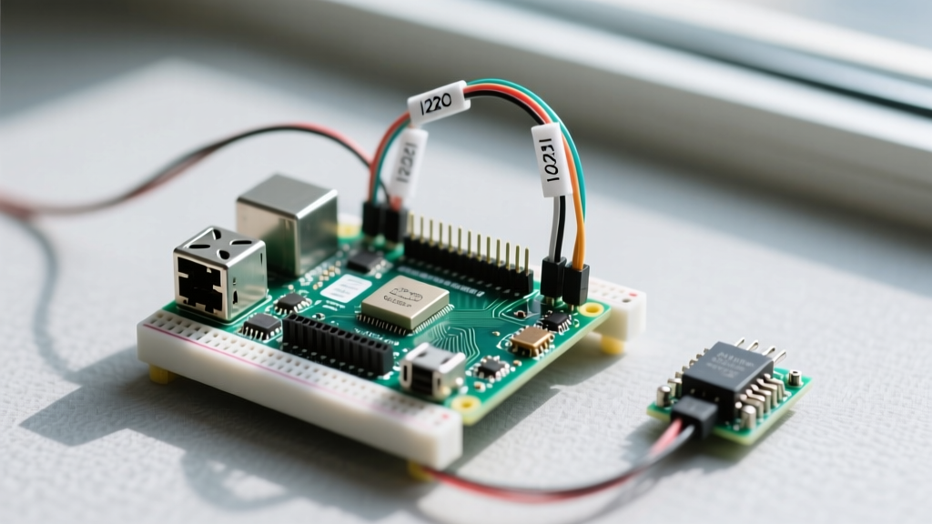
While solderless breadboards are not intended for permanent, in-wall deployments due to oxidation and vibration sensitivity, they are an indispensable first step in smart home engineering. Prototyping on a breadboard allows you to validate I2C address spaces, test pull-up resistor requirements, and debug Python sensor scripts before committing to a soldered perfboard or custom PCB. Furthermore, utilizing a Raspberry Pi Zero 2 W mounted directly to a breadboard via a GPIO breakout board minimizes parasitic capacitance and keeps jumper wire runs short, which is critical for high-speed digital protocols.
Hardware Bill of Materials (BOM) for Custom Nodes
Building a robust environmental and actuator node requires careful component selection. Cheap clone sensors often lack necessary voltage regulation, leading to erratic readings. Below is a curated BOM for a high-reliability smart home node.
| Component | Recommended Model / Spec | Est. Price | Role in Smart Home Node |
|---|---|---|---|
| SBC | Raspberry Pi Zero 2 W | $15.00 | Low-power compute, runs MQTT & Python scripts |
| Breadboard | Half-Size Solderless (400 tie points) | $4.50 | Prototyping footprint, fits inside standard enclosures |
| Env. Sensor | Bosch BME280 (I2C variant) | $10.00 | High-accuracy temp, humidity, and barometric pressure |
| Actuator | 4-Channel Optocoupler Relay (5V) | $6.00 | Galvanic isolation for switching 120V/240V loads |
| Logic Shifter | TXS0108E Bi-directional Converter | $3.50 | Protects Pi 3.3V logic from 5V sensor feedback |
| Power | Official Pi 27W USB-C PSU | $12.00 | Prevents brownouts during relay coil energization |
Wiring I2C Environmental Sensors (BME280 Deep Dive)
The BME280 is the gold standard for indoor climate monitoring, vastly outperforming the cheaper DHT11/DHT22 sensors in both accuracy and I2C bus stability. When wiring the BME280 to your Raspberry Pi and breadboard, you must utilize the primary I2C bus located on Pins 3 (SDA) and 5 (SCL).
Pinout and Pull-Up Resistor Dynamics
- Pin 1 (3.3V): Powers the BME280 breakout. Do not use 5V unless your specific breakout board features an onboard linear regulator (like the Adafruit version).
- Pin 3 (GPIO 2 / SDA): Serial Data line.
- Pin 5 (GPIO 3 / SCL): Serial Clock line.
- Pin 6 (GND): Common ground reference.
Expert Insight: The Raspberry Pi features internal 1.8kΩ pull-up resistors on the I2C bus. However, many generic breadboard BME280 modules also include 10kΩ pull-up resistors. When wired in parallel, the net resistance drops. While 1.5kΩ is generally acceptable for 100kHz I2C, adding multiple sensors to the same breadboard rails can degrade the signal edges, causing Remote I/O error timeouts in Python. If you are daisy-chaining sensors, use a dedicated I2C multiplexer like the TCA9548A to isolate bus capacitance.
Critical Warning: 3.3V Logic vs 5V Tolerance
The Raspberry Pi GPIO operates strictly at 3.3V logic. Feeding a 5V signal directly into a BCM2710 or BCM2711 SoC pin will cause catastrophic silicon failure, permanently destroying the Pi. Always use a logic level shifter (like the BSS138 MOSFET-based TXS0108E) when interfacing with 5V Arduino-style sensors or modules that output 5V on their data lines.
Actuator Control: Driving Relays Safely via GPIO
A common and destructive beginner mistake is attempting to drive a 5V relay coil directly from a Pi GPIO pin. The Pi's GPIO pins can safely source or sink only ~16mA each, with a total bank limit of 50mA. A standard Songle SRD-05VDC-SL-C relay coil requires roughly 70mA to energize. Attempting this will instantly trip the Pi's internal over-current protection or fry the GPIO pad.
Flyback Diodes and Optocoupler Isolation
To safely integrate heavy loads into your smart home, use an optocoupler-isolated relay module. These modules feature an internal PC817 optocoupler and a flyback diode across the relay coil. The flyback diode is crucial; when the relay coil de-energizes, it generates a massive reverse voltage spike (inductive kickback). Without the diode, this spike would arc back into your breadboard rails and reset the Pi.
With an optocoupler module, the Pi's 3.3V GPIO pin only needs to sink ~2mA to illuminate the internal LED, keeping the high-current 5V coil circuit completely galvanically isolated from the Pi's sensitive logic. Connect the relay module's VCC to the Pi's 5V pin (Pin 2), GND to Pin 9, and the IN1 control pin to GPIO 17 (Pin 11).
Bridging Hardware to Home Assistant via MQTT
Once your Raspberry Pi and breadboard hardware is validated, the next step is integrating it into your smart home ecosystem. While REST APIs are common, MQTT (Message Queuing Telemetry Transport) is vastly superior for low-latency, low-bandwidth sensor telemetry.
Using the Python paho-mqtt and smbus2 libraries, you can publish JSON payloads directly to a Mosquitto broker running on your Home Assistant server. Below is the architectural flow for a BME280 node:
- Initialize the I2C bus using
smbus2and read the BME280 calibration registers. - Calculate compensated temperature and humidity values.
- Format the data into a JSON string:
{"temp": 22.4, "hum": 45.2}. - Publish to the topic
homeassistant/sensor/node1/bme280/statewith the retain flag set toTrue.
Home Assistant's MQTT Integration will automatically parse this payload, allowing you to trigger automations—such as turning on a humidifier via your breadboard relay—when humidity drops below 40%.
Common Failure Modes and Troubleshooting Matrix
Working with a Raspberry Pi and breadboard introduces physical variables that purely software-based smart home hubs do not face. Below is a troubleshooting matrix based on real-world deployment failures.
| Symptom | Root Cause | Hardware / Software Fix |
|---|---|---|
| Pi randomly reboots when relay triggers | Voltage brownout on the 5V rail due to relay coil current spike. | Upgrade to a 3A+ power supply; add a 1000µF decoupling capacitor across the breadboard 5V/GND rails. |
OSError: [Errno 121] Remote I/O error |
I2C bus lockup caused by loose breadboard contacts or missing pull-ups. | Verify BME280 address with i2cdetect -y 1; replace oxidized jumper wires; ensure SDA/SCL are firmly seated. |
| Erratic / floating GPIO relay states | GPIO pin left in a high-impedance state during Pi boot sequence. | Enable internal pull-down resistors in software, or wire a 10kΩ external pull-down resistor from the GPIO pin to GND. |
| Sensor readings drift over 24 hours | BME280 self-heating due to continuous high-over-sampling mode. | Reduce IIR filter coefficient and oversampling rate in Python; implement a 10-second sleep between reads. |
Moving from Breadboard to Permanent Deployment
Once your smart home logic is proven on the breadboard, it is time to retire the temporary wiring. Solderless breadboards are prone to thermal expansion and contraction, which can slowly push jumper wires out of the spring clips over months of operation. For permanent in-wall or attic deployments, transfer your exact breadboard layout to a protoboard (perfboard) using 24 AWG solid-core wire. For the ultimate professional finish, design a custom PCB using KiCad, integrating the Raspberry Pi compute module or a direct ESP32 fallback for distributed smart home sensing.
For deeper technical specifications on the Pi's pinout and power delivery, always refer to the official Raspberry Pi hardware documentation, and consult the Adafruit BME280 wiring guides for sensor-specific I2C nuances.