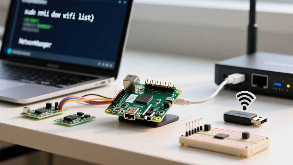
The Raspberry Pi 3 (Model B and B+) utilizes a 40-pin GPIO header. Pin 1 is the 3.3V pin located at the top-left when the board is oriented with the USB ports facing you and the GPIO header on the top right. Unlike microcontrollers with 5V-tolerant logic, the Pi 3's BCM2837 SoC operates strictly at 3.3V; applying 5V to any GPIO pin will permanently destroy the processor. Below is the complete hardware reference, followed by wiring standards and a concrete decision matrix for your next build.
The Complete 40-Pin GPIO Raspberry Pi 3 Pinout Table
This spec-sheet-table maps the physical header. The left bank represents odd pins (closest to the board edge), and the right bank represents even pins.
| Pin | Function / Label | BCM GPIO | Pin | Function / Label | BCM GPIO |
|---|---|---|---|---|---|
| 1 | 3.3V Power | - | 2 | 5V Power | - |
| 3 | I2C SDA1 | GPIO 2 | 4 | 5V Power | - |
| 5 | I2C SCL1 | GPIO 3 | 6 | Ground (GND) | - |
| 7 | General GPIO | GPIO 4 | 8 | UART TXD | GPIO 14 |
| 9 | Ground (GND) | - | 10 | UART RXD | GPIO 15 |
| 11 | General GPIO | GPIO 17 | 12 | PWM0 / PCM | GPIO 18 |
| 13 | General GPIO | GPIO 27 | 14 | Ground (GND) | - |
| 15 | General GPIO | GPIO 22 | 16 | General GPIO | GPIO 23 |
| 17 | 3.3V Power | - | 18 | General GPIO | GPIO 24 |
| 19 | SPI MOSI | GPIO 10 | 20 | Ground (GND) | - |
| 21 | SPI MISO | GPIO 9 | 22 | General GPIO | GPIO 25 |
| 23 | SPI SCLK | GPIO 11 | 24 | SPI CE0 | GPIO 8 |
| 25 | Ground (GND) | - | 26 | SPI CE1 | GPIO 7 |
| 27 | HAT ID_SD | GPIO 0 | 28 | HAT ID_SC | GPIO 1 |
| 29 | General GPIO | GPIO 5 | 30 | Ground (GND) | - |
| 31 | General GPIO | GPIO 6 | 32 | PWM0 | GPIO 12 |
| 33 | PWM1 | GPIO 13 | 34 | Ground (GND) | - |
| 35 | SPI1 MISO | GPIO 19 | 36 | SPI1 CE2 | GPIO 16 |
| 37 | General GPIO | GPIO 26 | 38 | SPI1 MOSI | GPIO 20 |
| 39 | Ground (GND) | - | 40 | SPI1 SCLK | GPIO 21 |
DC Color Codes: IEC vs. NEC vs. Standard Ribbons
When wiring custom harnesses, terminal blocks, or PCBs that interface with the Pi's GPIO, you must adhere to low-voltage DC color standards. Standard 40-pin rainbow ribbon cables are notorious for causing errors because they prioritize aesthetics over electrical code. Here is how regional standards apply to Pi projects:
| Standard | Region / Scope | Positive (+VDC) | Negative / Ground (0V) | Application to Pi 3 |
|---|---|---|---|---|
| IEC 60446 | EU / International | Brown | Blue | Use Brown for 3.3V/5V, Blue for GND on custom screw terminals. |
| US NEC (Art. 250/480) | North America | Red (or Black) | Black (or White/Grey) | Use Red for 5V, Black for GND. White is rarely used in 3.3V logic. |
| Old UK Standard | Pre-2004 UK | Red | Black | Matches standard Dupont jumper wire conventions. |
| Rainbow Ribbon | Hobbyist Default | Red (usually Pin 1) | Black (usually Pin 2) | Warning: Pin 1 is 3.3V, Pin 2 is 5V. Do not assume Red = 5V on ribbons. |
The 'Fried Pi' Trap: Rows Makers Get Wrong
According to community failure logs on Pinout.xyz, the vast majority of dead Pi 3 boards share three specific wiring mistakes. Understanding these rows is critical for hardware survival.
- The 5V vs 3.3V Swap (Pins 1, 2, 4, 17): The Pi's 5V pins (2 and 4) are directly tied to the USB power input. They can supply significant current but have zero regulation for logic. The 3.3V pins (1 and 17) are regulated. Feeding 5V into a GPIO pin (like Pin 3) bypasses internal protection diodes and instantly fries the BCM2837 SoC.
- The UART Cross-Wire (Pins 8 and 10): Pin 8 is TXD (Transmit) and Pin 10 is RXD (Receive). Makers frequently wire TX to TX and RX to RX. You must cross the lines: Pi TX (8) goes to Peripheral RX, and Pi RX (10) goes to Peripheral TX.
- The HAT EEPROM Pins (Pins 27 and 28): GPIO 0 (ID_SD) and GPIO 1 (ID_SC) are reserved for the HAT identification I2C bus. They have onboard pull-ups and are read at boot. Do not use these for general-purpose I/O or you will cause boot failures or I2C bus contention.
- Missing I2C Pull-ups: Pins 3 (SDA) and 5 (SCL) already have 1.8kΩ pull-up resistors to 3.3V on the Pi board. If your sensor module also has pull-ups, the combined resistance may drop too low, causing signal degradation. Always check your sensor module for jumper pads to disable duplicate pull-ups.
Decision Tree: Which GPIO Pin Should You Use?
Do not pick pins randomly based on physical convenience. Use this decision-tree-table to select the correct hardware-backed pins for your protocol, terminating in the exact pin and required support component.
| If your project needs... | Then choose Protocol... | Concrete Pin Pick (Physical) | Required Support Component / Note |
|---|---|---|---|
| Basic on/off switching (relays, LEDs) | Digital Output | Pins 11, 13, 15, 16, 18 (GPIO 17, 27, 22, 23, 24) | Use a 2N2222 transistor or ULN2003 driver; never drive >16mA directly from the pin. |
| Connecting OLEDs, BME280, or IMUs | I2C | Pins 3 (SDA) & 5 (SCL) | No external pull-ups needed (Pi has 1.8kΩ onboard). Ensure device is 3.3V tolerant. |
| High-speed displays or ADC chips | SPI0 | Pins 19, 21, 23, 24 (MOSI, MISO, SCLK, CE0) | Use a logic level shifter (e.g., SN74LVC8T245) if interfacing with 5V SPI devices. |
| Motor control, servos, or dimming | Hardware PWM | Pin 12 (GPIO 18) or Pin 32 (GPIO 12) | These are the only true hardware PWM pins. All others rely on CPU-timed software PWM. |
| GPS modules, serial consoles | Hardware UART | Pins 8 (TX) & 10 (RX) | Must disable serial console in raspi-config to free up /dev/ttyAMA0. |
Safe Interpretation When Header Markings Are Faded
On older Pi 3 boards, or when using third-party clone boards with poor silkscreen printing, the 'Pin 1' indicator may be invisible. Guessing incorrectly and applying 5V to Pin 2 while thinking it is Ground will destroy the board. Use these physical landmarks to verify orientation:
- The Square Pad Method (Most Reliable): Flip the Raspberry Pi over and look at the solder joints on the underside of the GPIO header. Pin 1 is the only pin with a square solder pad. Every other pin (2 through 40) has a perfectly round solder pad.
- The Component Edge Method: Orient the board so the USB and Ethernet ports are facing toward you. The GPIO header runs along the top right edge. Pin 1 is always the top-left pin of that header block (closest to the SD card slot and the main CPU).
- The Continuity Test: If the board is unpowered and you have a multimeter, set it to continuity mode. Probe the metal shielding of the USB ports (which is tied to Ground) and test the suspected ground pins (6, 9, 14, 20, 25, 30, 34, 39). Once you map the grounds, you can mathematically deduce the remaining pins based on the 40-pin layout table above.
For comprehensive schematic details and official hardware specifications, always refer to the official Raspberry Pi documentation. When in doubt, default to IEC/NEC color standards for custom wiring, verify Pin 1 via the square solder pad, and never exceed 3.3V on any BCM GPIO pin.