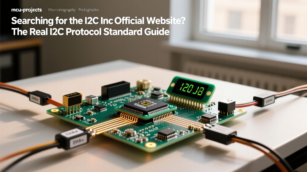

Many makers and junior engineers hit a wall searching for an I2C Inc official website to download the latest bus specifications or register a device address. Here is the bench-truth: there is no standalone "I2C Inc." governing body like the USB-IF or the Bluetooth SIG. The Inter-Integrated Circuit (I2C) protocol was invented by Philips in 1982, and the intellectual property and official standard are now maintained by NXP Semiconductors. If you want the definitive I2C-bus specification and user manual, the NXP UM10204 documentation is your actual official source.
I2C is a synchronous, multi-master, multi-slave serial communication bus that uses just two bidirectional open-drain lines: Serial Data (SDA) and Serial Clock (SCL). It is the undisputed workhorse for onboard sensor networks, EEPROMs, and GPIO expanders. But because it relies on open-drain physics rather than push-pull drivers, it is uniquely prone to physical layer failures. Let us break down the exact mechanics, wiring rules, and debugging tactics you need to make your next embedded project work on the first try.
I2C Bus Mechanics and Physical Layer Specs
Before writing a single line of code, you must understand the electrical reality of the bus. I2C uses open-drain (or open-collector) outputs. This means devices can pull the line LOW to GND, but they cannot drive it HIGH. To achieve a HIGH state, the bus relies entirely on external pull-up resistors tied to VCC. This architecture allows multiple devices to share the same wires without short-circuiting when one drives high and another drives low (a wired-AND configuration).
| Speed Mode | Bit Rate | Max Bus Capacitance | Addressing Scheme | Practical Max Distance |
|---|---|---|---|---|
| Standard-mode (Sm) | 100 kbit/s | 400 pF | 7-bit (112 addrs) / 10-bit | ~1 meter (unshielded) |
| Fast-mode (Fm) | 400 kbit/s | 400 pF | 7-bit / 10-bit | ~0.5 meters |
| Fast-mode Plus (Fm+) | 1 Mbit/s | 550 pF | 7-bit / 10-bit | ~0.3 meters |
| High-speed mode (Hs) | 3.4 Mbit/s | 170 pF | 7-bit / 10-bit + Master Code | ~0.1 meters (PCB traces) |
Protocol Showdown: I2C vs. SPI vs. UART
Choosing the right protocol depends entirely on your constraints regarding distance, speed, and device count. Here is how I2C stacks up against the other heavyweight serial protocols when designing a system architecture.
| Feature | I2C | SPI | UART (w/ RS-485) |
|---|---|---|---|
| Wires Required | 2 (SDA, SCL) | 4+ (MOSI, MISO, SCK, CS) | 2 (TX, RX) + Differential pair |
| Device Count | Up to 112 (7-bit bus) | Limited by CS pins / Daisy chain | Point-to-point (1:1) or Multi-drop RS-485 |
| Max Speed (Typical) | 400 kHz (Fast) / 3.4 MHz (HS) | 10 MHz to 100+ MHz | 1 Mbps (Standard UART) |
| Max Distance | < 1 meter (on-board) | < 0.5 meters (on-board) | Up to 1200 meters (RS-485) |
| Best Use Case | Low-speed sensors, EEPROMs, GPIO expanders | High-speed ADCs, displays, flash memory | Long-distance industrial, GPS modules, debug consoles |
When to choose which: Choose I2C when you have many low-speed sensors on the same PCB and want to minimize trace routing. Choose SPI when you are pushing pixels to an LCD or reading high-sample-rate ADCs where I2C's 400 kHz ceiling would bottleneck your data. Choose UART (specifically mapped to RS-485 transceivers) when your sensor is located 50 meters away in a noisy industrial environment.
Wiring, Code, and Minimal Working Exchange
Let us wire an ESP32 DevKit V1 to a Bosch BME280 environmental sensor. A common mistake is assuming all breakout boards have pull-up resistors populated. Adafruit and SparkFun boards do; generic unbranded boards from bulk marketplaces often do not. Always check the schematic or measure the SDA/SCL lines to VCC with a multimeter (you should read the pull-up resistance value, typically 4.7kΩ or 10kΩ).
Physical Wiring Map
| ESP32 DevKit V1 Pin | BME280 Breakout Pin | Notes |
|---|---|---|
| 3V3 | VIN / VCC | Do NOT use 5V; BME280 logic is strictly 3.3V. |
| GND | GND | Ensure a solid common ground. |
| GPIO 21 (SDA) | SDI / SDA | Add 4.7kΩ pull-up to 3V3 if missing on breakout. |
| GPIO 22 (SCL) | SCK / SCL | Add 4.7kΩ pull-up to 3V3 if missing on breakout. |
Minimal Arduino/ESP32 I2C Exchange
This code initializes the bus, forces 400 kHz Fast-mode, and reads the BME280 chip ID register (0xD0) which should always return 0x60. Notice the explicit error handling on Wire.endTransmission()—this is critical for preventing hard locks when a device fails to ACK.
#include <Wire.h>

const uint8_t BME280_ADDR = 0x76; // 0x77 if SDO pin is tied to VCC
const uint8_t REG_CHIP_ID = 0xD0;

void setup() {
  Serial.begin(115200);

  // Initialize I2C on ESP32 default pins (SDA=21, SCL=22)
  Wire.begin();
  Wire.setClock(400000); // Force Fast-mode (400 kHz)

  delay(100); // Allow bus to stabilize
}

void loop() {
  Wire.beginTransmission(BME280_ADDR);
  Wire.write(REG_CHIP_ID); // Point to the Chip ID register

  uint8_t error = Wire.endTransmission(false); // Send repeated start

  if (error != 0) {
    Serial.print("I2C Bus Error Code: ");
    Serial.println(error); // 2 = NACK on address, 3 = NACK on data
    delay(2000);
    return;
  }

  Wire.requestFrom(BME280_ADDR, (uint8_t)1);
  if (Wire.available()) {
    uint8_t chipID = Wire.read();
    Serial.print("BME280 Chip ID: 0x");
    Serial.println(chipID, HEX); // Should print 0x60
  }

  delay(1000);
}
Debugging the Bus: Classic Failures and Sniffing
When your I2C bus hangs or returns garbage data, the issue is almost always at the physical layer. Here is how to diagnose the three classic I2C failures, and how to sniff the bus when the multimeter is not enough.
1. The Missing or Weak Pull-Up
Symptom: Wire.endTransmission() returns 0 (success), but Wire.read() returns 0xFF or random noise. The bus feels "sluggish" at higher speeds.
The Physics: Without pull-ups, the lines float. The internal weak pull-ups of the ESP32 (around 45kΩ) are far too weak to overcome the bus capacitance at 400 kHz, resulting in rounded, shark-fin shaped voltage rises that fail to cross the $V_{IH}$ (Input High Voltage) threshold before the next clock edge.
The Fix: Solder 4.7kΩ or 2.2kΩ axial resistors between SDA/SCL and VCC. Verify with an oscilloscope that the rise time ($t_r$) is under 300ns for Fast-mode.
2. Address Clashes
Symptom: Two identical sensors (e.g., two BME280s) on the same bus. Both default to 0x76. The microcontroller reads a mashed-up collision of data from both chips trying to pull SDA low simultaneously.
The Fix: Check the datasheet for an address-select pin. On the BME280, tying the SDO pin to GND sets the address to 0x76; tying it to VCC sets it to 0x77. If the module lacks address pins, use an I2C multiplexer like the TI PCA9548A to route the bus to isolated downstream channels.
3. Clock Stretching and Baud Mismatch
Symptom: The bus locks up entirely. SCL is held LOW indefinitely.
The Physics: Clock stretching is a feature where a slow slave device pulls SCL low to force the master to wait while it processes data. If the master (like an ESP32 using certain hardware I2C peripherals) has a strict timeout or does not support stretching, it will abort or hang.
The Fix: Increase the I2C timeout value in your library, or switch to a software I2C implementation (bit-banging) which handles stretching more gracefully.
How to Sniff and Decode the Bus
When logic fails, you must look at the raw waveforms. Connect a Saleae Logic Analyzer or a standard digital storage oscilloscope (DSO) to SDA and SCL.
- Trigger Condition: Set your scope to trigger on a falling edge on SDA while SCL is HIGH. This is the universal I2C START condition.
- Decode: Use the scope's built-in I2C decode bus feature. Set the threshold to 50% of VCC (1.65V for a 3.3V system).
- Verify ACK/NACK: Look at the 9th clock cycle. The master releases SDA. If the slave pulls SDA LOW, that is an ACK (success). If SDA stays HIGH, that is a NACK (device missing or busy).
Mastering I2C requires moving beyond the Arduino Wire library abstractions and understanding the open-drain physics governing the bus. Keep the NXP UM10204 spec sheet bookmarked, respect the capacitance limits, and always verify your pull-ups before writing complex driver code.