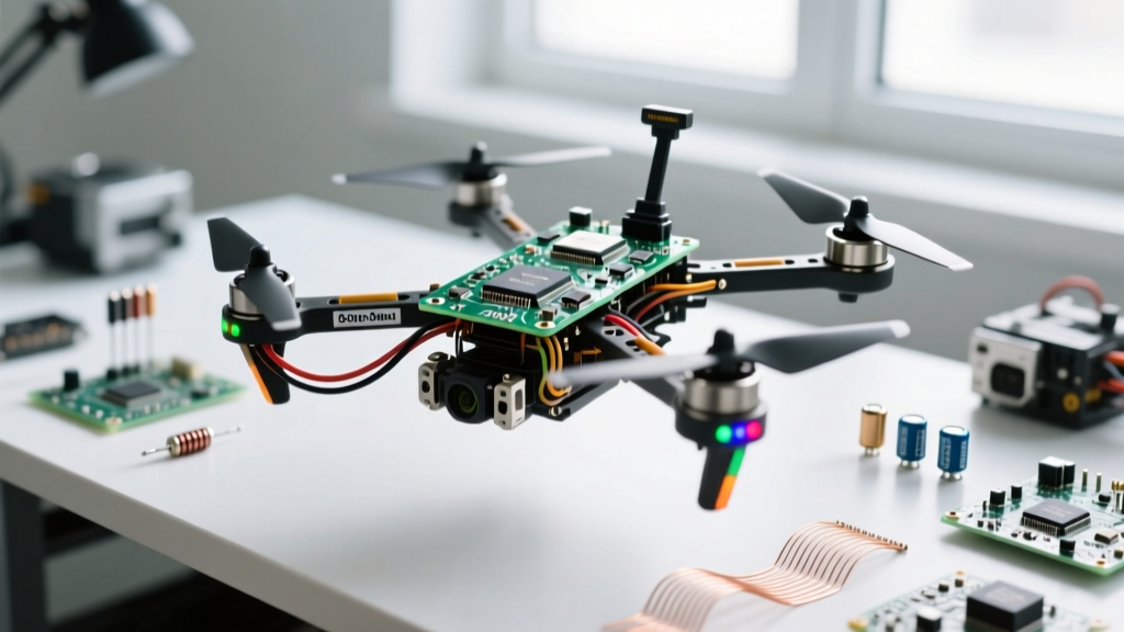

When electrical engineers and robotics developers ask, what is a quadcopter, the consumer-grade answer is simply a flying drone with four propellers. However, from an advanced build and systems-engineering perspective, a quadcopter is a highly complex, underactuated, non-holonomic robotic platform. It relies on rapid differential thrust vectoring and gyroscopic torque manipulation to maintain stability in three-dimensional space. Building a high-performance quadcopter in 2026 requires moving far beyond plug-and-play kits; it demands a deep understanding of microcontroller architectures, digital ESC protocols, kinematic control loops, and custom power distribution networks.
Defining the Quadcopter: Beyond the Basic Four-Motor Topology
At its core, a quadcopter utilizes four fixed-pitch rotors. Unlike traditional helicopters that rely on complex swashplates and variable blade pitch, a quadcopter alters its attitude and trajectory purely by modulating the RPM of its brushless DC (BLDC) motors. The rotors are configured in two counter-rotating pairs (typically two clockwise and two counter-clockwise). This configuration cancels out the net aerodynamic torque (yaw) when all motors spin at an equal base speed. To induce a yaw rotation, the flight controller (FC) increases the speed of one diagonal pair while decreasing the other, leveraging Newton's third law of motion to rotate the airframe around the Z-axis.
Understanding the fundamental copter architecture is critical before selecting components. Because the system is underactuated—meaning it has six degrees of freedom (6DOF) but only four independent control inputs—it cannot translate laterally without first tilting its thrust vector. This inherent coupling of pitch/roll and translational movement is why the flight controller's sensor fusion and PID loop latency must be measured in microseconds, not milliseconds.
Core Avionics: Selecting the Flight Controller and IMU
The brain of any advanced quadcopter is the Flight Controller (FC). For high-performance builds, the industry standard has shifted from the STM32F405 to the STM32H743 microcontrollers. The H7 series operates at 480 MHz, providing the massive computational headroom required for advanced gyro filtering, bidirectional DShot decoding, and complex Kalman filtering without overloading the CPU.
Equally important is the Inertial Measurement Unit (IMU). While older builds relied on the MPU6000, advanced 2026 builds utilize the TDK ICM-42688-P. This MEMS sensor supports SPI bus clock speeds up to 24 MHz and offers significantly lower noise floors at high polling rates (8 kHz to 32 kHz). When designing or selecting an FC, ensure the IMU is mounted on an internal vibration-damping gel or suspended via silicone O-rings to isolate it from high-frequency frame resonances, which can otherwise alias into the gyro data and cause catastrophic motor desyncs.
Propulsion and Telemetry: DShot Protocol and ESC Telemetry
Propulsion selection dictates the entire power envelope of the quadcopter. For a 5-inch to 7-inch advanced freestyle or cinematic build, the sweet spot is a 2207 or 2306 stator size with a KV rating between 1700 and 1900, paired with a 6S LiPo (22.2V nominal). Motors like the T-Motor F60 Pro IV utilize N52H arc magnets and single-strand windings to maximize copper fill factor, reducing internal resistance (Rm) and improving thermal dissipation during high-load maneuvers.
Communicating with the Electronic Speed Controllers (ESCs) is no longer done via analog PWM. Advanced builds mandate the use of digital protocols, specifically Bidirectional DShot. This protocol sends digital packets to the ESC while simultaneously receiving telemetry data back, allowing the FC to read the exact electrical RPM of every motor in real-time.
Table: Advanced ESC Protocol Comparison
| Protocol | Signal Type | Max Update Rate | Telemetry | Calibration Required? |
|---|---|---|---|---|
| Standard PWM | Analog Pulse | ~500 Hz | No | Yes |
| Multishot | Analog Pulse | ~32 kHz | No | Yes |
| DShot300 | Digital | 300 kbit/s | No (Unidirectional) | No |
| DShot600 | Digital | 600 kbit/s | Yes (Bidirectional) | No |
| ProShot 1000 | Digital | 1000 kbit/s | Experimental | No |
Kinematic Control: PID Tuning and Filter Stacks
Once the hardware is integrated, the true engineering challenge begins in the software. Using firmware like Betaflight, developers must tune the Proportional-Integral-Derivative (PID) controller. In a quadcopter, the 'P' term fights external disturbances (like wind), the 'I' term maintains the setpoint over time (preventing drift), and the 'D' term acts as a damper to prevent overshoot during rapid stick inputs.
However, raw PID tuning is impossible without a robust filter stack. Every carbon fiber frame has mechanical resonance frequencies, typically between 100 Hz and 300 Hz. If these vibrations reach the IMU, the 'D' term will amplify them, leading to hot motors and eventual thermal failure. Advanced builders utilize Blackbox logging to perform Fast Fourier Transform (FFT) analysis on the gyro data. By identifying the exact noise peaks, you can configure Dynamic Notch Filters that track and eliminate these specific frequencies in real-time, keeping the PID loop clean and the motors running cool.
Power Distribution and Custom PDB Design
A frequently overlooked aspect of answering 'what is a quadcopter' from an electrical standpoint is the Power Distribution Board (PDB). When four BLDC motors pull 35 amps each simultaneously, the system experiences massive transient current spikes exceeding 140 amps. Standard 1oz copper PCB traces will suffer from severe voltage sag and potential delamination.
Expert Insight on VBAT Sag: 'Always design or select a 4-in-1 ESC with at least 2oz copper weight on the inner power layers. Furthermore, integrate a low-ESR (Equivalent Series Resistance) bulk capacitor bank—such as 1000µF 35V Panasonic capacitors—directly at the main battery leads. This acts as a localized energy reservoir, absorbing high-frequency voltage ripple and protecting the FC's sensitive 5V and 3.3V BECs from inductive kickback.'
For custom builds, integrating a Transient Voltage Suppression (TVS) diode across the main VBAT and GND pads is a critical safeguard against voltage spikes generated during hard braking or motor desync events.
Assembly, Resonance Testing, and Failure Mode Mitigation
The final phase of an advanced build involves physical resonance mitigation. Hard-mounting the FC directly to the carbon fiber frame guarantees that high-frequency motor noise will corrupt the IMU data. Instead, use specialized silicone grommets with a durometer rating of 40A to 50A to soft-mount the flight controller. This creates a mechanical low-pass filter, physically isolating the IMU from vibrations above 80 Hz.
Before the maiden flight, conduct a bench test using the configurator's motor tab to spin the motors at 15% and 30% throttle while monitoring the Blackbox FFT graph. If you observe massive noise spikes that the dynamic notch filters cannot suppress, you must address the mechanical root cause—often a bent motor shaft, unbalanced propellers, or loose arm hardware. By treating the quadcopter not just as a toy, but as a precision electromechanical instrument, you unlock flight dynamics, responsiveness, and reliability that commercial off-the-shelf drones simply cannot match.