
Moving Beyond the Breadboard: Real-World Temp Sensor Arduino Deployments
Most online tutorials for a temp sensor Arduino project stop at the breadboard phase. You wire a sensor to a 5V pin, read an analog value or a basic digital library, and print the result to the serial monitor. However, when you transition from a controlled desk environment to real-world applications—such as outdoor greenhouse monitoring, server rack thermal management, or home brewing fermentation chambers—the physics of wiring, electromagnetic interference (EMI), and power constraints quickly invalidate textbook examples.
Deploying temperature sensors in the field requires a deep understanding of bus capacitance, voltage drop, and microsecond-level timing interrupts. In this guide, we will dissect the two most common digital sensors used in Arduino ecosystems—the Maxim DS18B20 and the Aosong DHT22—and explore the engineering realities of deploying them outside the lab.
The Analog Trap: Why LM35 and TMP36 Fail in the Field
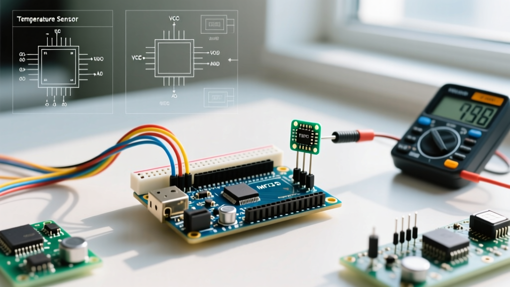
Before diving into digital solutions, it is crucial to address why analog sensors like the LM35 or TMP36 are generally unsuitable for remote field deployments. Analog sensors output a voltage proportional to the temperature (e.g., 10mV/°C for the LM35). While this is easy to read with an Arduino's onboard ADC, it introduces severe vulnerabilities over distance.
- Voltage Drop and Wire Resistance: Standard 24 AWG copper wire has a resistance of roughly 84 ohms per 1000 feet. While the current draw is low, the real issue is the voltage divider effect created by long wires and the ADC's internal sampling capacitor.
- EMI and Antenna Effects: A 3-meter run of unshielded analog wire acts as an antenna. In environments with switching power supplies, relays, or variable frequency drives (VFDs), the induced noise will cause wild fluctuations in your ADC readings.
- Reference Voltage Drift: If your Arduino is powered by a fluctuating battery or an unregulated solar charge controller, the 5V reference rail will drift. Since analog sensors rely on the ADC's reference voltage for calculation, a 0.2V drop in VCC translates directly to a massive temperature calculation error.
For any deployment where the sensor is more than 30 centimeters from the microcontroller, digital protocols are mandatory.
Digital Contenders: DS18B20 vs. DHT22 for Environmental Monitoring
When building a robust temp sensor Arduino network, the choice usually narrows down to the 1-Wire DS18B20 or the single-bus DHT22. Both transmit digital data, making them immune to the analog voltage drop issues mentioned above, but they operate on fundamentally different physical layers.
| Feature | Maxim DS18B20 | Aosong DHT22 (AM2302) |
|---|---|---|
| Protocol | 1-Wire (Dallas/Maxim) | Proprietary Single-Bus |
| Measurement | Temperature Only | Temperature & Humidity |
| Accuracy | ±0.5°C (from -10°C to +85°C) | ±0.2°C (Temp), ±2% (RH) |
| Max Wire Length | Up to 100m (with proper topology) | ~20m (highly dependent on cable) |
| Enclosure | Available in waterproof stainless steel | Plastic grid (indoor/enclosure only) |
| Bus Topology | Multi-drop (up to 50+ on one pin) | Point-to-point (one sensor per pin) |
DS18B20: The Liquid and Outdoor Workhorse
The DS18B20 is the undisputed king of liquid and outdoor temperature monitoring. Its unique 64-bit ROM serial number allows you to daisy-chain dozens of sensors on a single Arduino digital pin. However, the 1-Wire protocol is highly sensitive to bus capacitance. Every meter of cable adds picofarads (pF) of capacitance to the line. If the capacitance exceeds the pull-up resistor's ability to charge the line within the required microsecond timing windows, the CRC (Cyclic Redundancy Check) will fail, and the Arduino will drop the sensor.
DHT22 (AM2302): The Indoor Climate Standard
The DHT22 is excellent for indoor HVAC monitoring, incubators, and server rooms where both temperature and relative humidity are required. Unlike the 1-Wire protocol, the DHT22 uses a strict, non-addressable single-bus protocol that relies on the microcontroller pulling the line low and high for specific microsecond durations to initiate a read. This timing sensitivity makes the DHT22 notoriously difficult to use on RTOS-based boards like the ESP32 without dedicated interrupt handling or secondary co-processors.
Wiring Topologies and Pull-Up Resistor Calculations
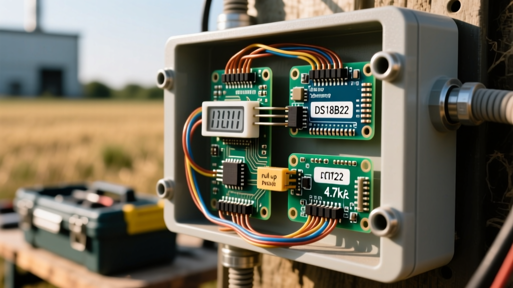
The most common cause of failure in real-world temp sensor Arduino projects is incorrect pull-up resistor sizing. The standard tutorial advice is to 'use a 4.7kΩ pull-up resistor.' This is only valid for short, breadboard-level wires.
According to the Analog Devices 1-Wire Guidelines, as cable length increases, the capacitance of the wire increases, slowing the rise time of the signal edge. To maintain a sharp rise time, you must lower the resistance to provide more current to charge the parasitic capacitance of the cable.
Field Rule of Thumb for DS18B20 Pull-Ups:
For runs under 5 meters, a 4.7kΩ resistor is fine.
For runs between 5 and 15 meters, drop to a 2.2kΩ or 1kΩ resistor.
For runs exceeding 15 meters, you must use an active pull-up circuit (a MOSFET-driven strong pull-up) to force the line high rapidly, as detailed in Paul Stoffregen's OneWire documentation.
Furthermore, never use standard ribbon cable for long 1-Wire runs. Use Cat5e or Cat6 twisted-pair Ethernet cable. Dedicate one pair to Ground and Data (twisted together to minimize inductive loops), and use another pair for VCC and Ground. This specific topology drastically reduces crosstalk and EMI susceptibility.
Troubleshooting Field Failures: -127°C and the 85°C Ghost
When deploying DS18B20 sensors, you will inevitably encounter two specific phantom readings that indicate underlying hardware or timing issues.
The 85°C Power-On Default
If your Arduino reads exactly 85°C upon booting or waking from deep sleep, you are reading the sensor's scratchpad before a temperature conversion has completed. 85°C is the factory default value in the DS18B20 scratchpad register. This happens when your code requests a temperature read immediately after applying power, bypassing the required 750ms conversion delay (for 12-bit resolution). Solution: Implement a non-blocking state machine using millis() that triggers the conversion, waits 750ms, and then reads the scratchpad.
The -127°C CRC Error
A reading of -127°C (or sometimes 255°C depending on the library) indicates a bus communication failure. The Arduino sent the read command, but the data returned failed the CRC check. This is almost always caused by:
- Bus capacitance being too high for the current pull-up resistor.
- Parasitic power mode failing. If you are using parasitic power (VCC tied to GND, drawing power from the data line), the line will droop during the 750ms conversion phase, causing the sensor to brown out. For long runs, always use VCC power mode.
- Corrupted data lines due to water ingress in outdoor junction boxes. Always use marine-grade heat shrink with adhesive lining on outdoor splices.
Power Consumption: Battery-Operated Arduino Sensor Nodes
When building off-grid, solar-powered Arduino weather stations, quiescent current draw is the enemy. The DHT22 requires a constant power supply and draws roughly 1.5mA when idle, which will drain a standard 18650 lithium cell over a few months if the node is not put to sleep.
Conversely, the DS18B20 draws less than 1µA in standby. However, to achieve true micro-power operation, you must power the sensor from a GPIO pin rather than the constant 3.3V/5V rail. By setting the GPIO pin HIGH to power the sensor, waiting for the conversion, reading the data, and then setting the GPIO LOW, you can reduce the sensor's average power draw to virtually zero between 15-minute logging intervals.
Final Deployment Checklist
Before sealing your enclosure and mounting your temp sensor Arduino project in the field, run through this E-E-A-T validated checklist:
- Cable Selection: Are you using twisted-pair cable for runs over 3 meters?
- Pull-Up Sizing: Have you calculated the pull-up resistor based on the total bus capacitance (pF) of your wire run?
- Timeout Handling: Does your code include a timeout mechanism to prevent the microcontroller from hanging if a DHT22 fails to respond to the handshake?
- Power Topology: Are your DS18B20 sensors wired in VCC mode rather than parasitic mode for runs over 5 meters?
- Environmental Sealing: If using a DHT22 outdoors, is it housed in a Stevenson screen or passive radiation shield to prevent solar loading and direct rain ingress?
By respecting the electrical realities of digital communication protocols, your temperature monitoring deployments will survive the transition from the workbench to the real world, providing years of reliable, drift-free data.