
Why Choose an I2C LCD Display for Your First Project?
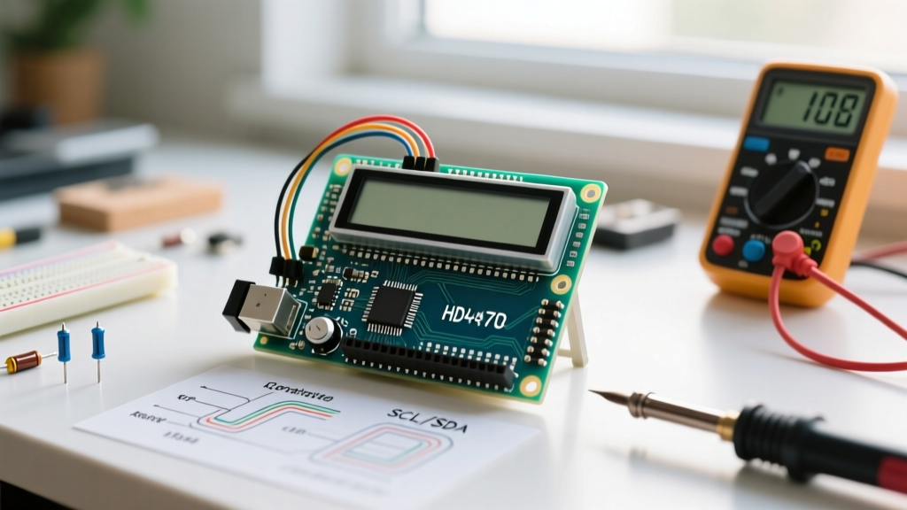
When beginners first start experimenting with microcontrollers like the Arduino Uno or ESP32, outputting data to a screen is a major milestone. The classic Hitachi HD44780 character LCD is the undisputed king of hobbyist displays. However, wiring a standard parallel LCD requires up to six digital GPIO pins, which quickly exhausts your available I/O on smaller boards. Enter the I2C LCD display. By utilizing a small backpack board equipped with an I/O expander chip, you can control a 16x2 or 20x4 character display using just two wires: SDA (Serial Data) and SCL (Serial Clock). This guide will walk you through the exact hardware anatomy, wiring matrices, address traps, and modern software libraries required to get your I2C LCD display running flawlessly on the first try.
The Anatomy of the I2C Backpack
To troubleshoot effectively, you must understand what is happening on the back of your display. The I2C backpack is a separate PCB soldered to the 16 pins of the LCD glass. It contains two primary components:
- The HD44780 Controller: Built into the LCD glass itself, this chip manages the character ROM, RAM, and the physical liquid crystal matrix.
- The I/O Expander (PCF8574 or MCP23008): This chip sits on the backpack. It receives 8-bit parallel data from the microcontroller via the I2C protocol and translates it into the parallel signals the HD44780 requires.
Most cheap displays imported from overseas use the NXP or Texas Instruments PCF8574 chip. Understanding this chip is critical because it dictates your I2C address, which is the number one reason beginners fail to get their displays working.
Hardware Wiring Matrix: Uno, Mega, and ESP32
Wiring an I2C LCD display is straightforward, but logic voltage levels vary between microcontroller families. The standard HD44780 LCD requires 5V for the backlight and logic. While an Arduino Uno operates at 5V, an ESP32 operates at 3.3V. Feeding 5V into an ESP32's I2C pins can permanently damage the silicon.
| Backpack Pin | Arduino Uno / Mega (5V Logic) | ESP32 / ESP8266 (3.3V Logic) | Notes & Best Practices |
|---|---|---|---|
| GND | GND | GND | Ensure a common ground reference. |
| VCC | 5V | 5V (VIN pin) | The LCD backlight requires 5V / 100mA+. |
| SDA | A4 (Uno) / Pin 20 (Mega) | GPIO 21 | Use 4.7kΩ pull-up resistors if wires exceed 12 inches. |
| SCL | A5 (Uno) / Pin 21 (Mega) | GPIO 22 | Do not use series resistors on I2C lines. |
Pro-Tip for ESP32 Users: If you are using a 3.3V microcontroller, power the LCD's VCC from the board's 5V VIN pin, but use a bidirectional logic level shifter (like the BSS138 MOSFET circuit) on the SDA and SCL lines to protect your ESP32 from the 5V pull-ups often found on cheap I2C backpacks.
The I2C Address Trap: Finding Your Hex Code
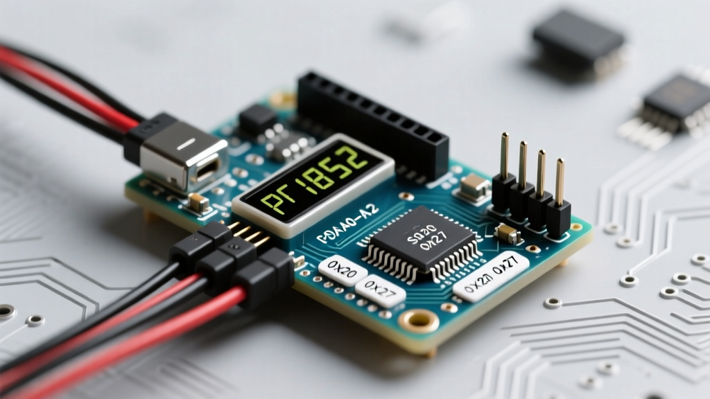
The most common beginner failure mode is a blank screen caused by an incorrect I2C address in the code. The PCF8574 chip has three address selection pads labeled A0, A1, and A2. By default, these are pulled high via jumpers, resulting in the base address 0x27.
However, some manufacturers use the PCF8574A variant instead. The 'A' variant has a different internal hardware offset, meaning its default address is 0x3F. If your code is hardcoded to 0x27 and your backpack uses the 'A' variant, the microcontroller will simply shout into the void.
Using the I2C Scanner Sketch
Never guess your address. Before writing your main application, upload the standard Arduino I2C Scanner sketch (found in the Arduino IDE under File > Examples > Wire > I2CScanner). Open the Serial Monitor at 9600 baud. The scanner will probe the bus and return the exact hexadecimal address of your display, usually outputting something like: I2C device found at address 0x3F.
Software Showdown: LiquidCrystal_I2C vs. hd44780
For years, the community relied on the LiquidCrystal_I2C library by Francisco Malpartida. While functional, it requires you to manually map the I2C expander pins to the LCD pins (e.g., En=2, Rw=1, Rs=0, D4=4, D5=5, D6=6, D7=7). If you buy a display from a different factory, the internal PCB routing might change, rendering your hardcoded pin map useless and leaving you with a blank screen.
The Modern Standard: In 2026, the undisputed best practice is to use the hd44780 library by Bill Perry. Specifically, the hd44780_I2Cexp class. This library is a masterpiece of engineering; it automatically scans the I2C bus, identifies the address, and dynamically probes the pin mappings of the backpack. It completely eliminates the 'wrong pin map' failure mode.
Installation and Code Implementation
Open the Arduino IDE Library Manager, search for hd44780 by Bill Perry, and install it. Below is the bulletproof initialization code for a 16x2 I2C LCD display:
#include <Wire.h>
#include <hd44780.h>
#include <hd44780ioClass/hd44780_I2Cexp.h>

// Automatically detects address and pin mapping
hd44780_I2Cexp lcd;

const int LCD_COLS = 16;
const int LCD_ROWS = 2;

void setup() {
  // Initialize LCD with auto-detection
  int status = lcd.begin(LCD_COLS, LCD_ROWS);

  if (status) {
    // If initialization fails, blink the onboard LED to indicate error
    hd44780::fatalError(status);
  }

  lcd.print('ElectricalFlux');
  lcd.setCursor(0, 1);
  lcd.print('I2C LCD Guide');
}

void loop() {
  // Main application logic here
}
Diagnostic Matrix: Troubleshooting Common Failures
Even with the correct wiring and the hd44780 library, physical hardware quirks can cause issues. Use this diagnostic matrix to solve physical layer problems.
| Symptom | Root Cause | Solution |
|---|---|---|
| Top row shows solid black boxes | Contrast voltage (V0) is too high. | Turn the blue trimpot on the back of the I2C backpack counter-clockwise using a small Phillips screwdriver until characters appear. |
| Display is completely blank, no backlight | Backlight jumper is open or VCC is missing. | Check for 5V on the VCC pin. Ensure the 'LED' jumper pad on the backpack is bridged with solder. |
| Text is correct but randomly flickers | I2C bus noise or missing pull-up resistors. | Add 4.7kΩ pull-up resistors between SDA/SCL and VCC. Keep I2C wires under 30cm (12 inches). |
| Library reports 'No devices found' | SDA/SCL swapped or dead I2C expander. | Swap SDA and SCL wires. Verify VCC is reaching the PCF8574 chip. Check for cold solder joints on the 16-pin header. |
Final Thoughts on Peripheral Integration
Mastering the I2C LCD display is a rite of passage for electronics hobbyists. It teaches you the fundamentals of bus protocols, address mapping, and hardware-software abstraction. By moving away from legacy hardcoded libraries and embracing auto-detecting frameworks like hd44780, you spend less time debugging phantom pin mappings and more time building actual projects. Whether you are building a DIY weather station, a 3D printer controller, or a smart home dashboard, a properly configured I2C character display remains one of the most reliable, low-latency user interfaces available in the embedded world.